What Goes Into Rugged Electronics Design?

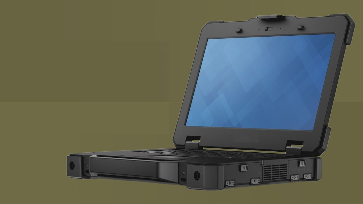
Try searching for “rugged electronics” on the internet, and you’ll probably find a lot of videos showing people stepping on their smartphones. Rugged electronics need to take a punch mechanically, but there is more that goes into a rugged system than being able to survive a drop on the pavement. This is as much about enclosure design as it is about component selection and manufacturing choices.
Mil-aero designers often use the term “harsh environment” to describe a number of scenarios where an electronic device’s reliability and lifetime will be put to the test. If you want to make your next product truly rugged, it helps to adopt some of their strategies in your PCB layout. In this article, we’ll look at some of the design strategies used in mil-aero designs, as well as strategies used for industrial designs.
What Qualifies as a Harsh Environment in Rugged Electronics?
The term “environment” as defined in some industry standards can refer to anything from actual environmental conditions (temperature, humidity, etc.) to the mechanical environment (e.g., vibration) or electrical environment (noise, potential for ESD). Rugged electronics are typically designed to withstand one or more conditions typically found in harsh environments:
- Excessively high or low temperatures
- Extreme and frequent temperature cycling
- Moisture and high/low pressure
- Mechanical vibration or shock
- Electrical discharge at high voltage/current
- Particulates, such as dust
- Oxidizing or explosive gases
This is a pretty extensive and mind-boggling list. Generally, you can’t design a single device to withstand every factor in the above list. Harsh environments are difficult to deal with simply because there is such a broad range of factors that can destroy an electronic device. These problems could affect the board, components, the overall PCBA, or all of the above.
Some Ruggedization Strategies
The table below summarizes some of the solutions you can implement in your design to make it more rugged and better withstand the above list of environmental factors.
|
|
|
|
|
|
|
|
|
|
|
|
|
|
|
|
|
|
|
|
|
|
|
|
|
|
|
|
|
|
From the above table, it should be clear that ruggedization spans beyond the board level. Some solutions can only be implemented at the board level, while others require considering everything from board to components and the enclosure. Some of the industry standards that govern these solutions include:
- Ingress Protection (IP) standard, which limits moisture ingress in rugged electronics
- MIL-S-901D, specifying high-impact mechanical shock requirements for equipment on ships
- MIL-STD-810G, specifying testing requirements for military equipment that has been commercially adopted
- National Electrical Manufacturers Association (NEMA), specifying enclosures, cabinets and housings
- National Fire Protection Association (NFPA), specifying a range of requirements on electronics in certain environments to ensure fire suppression or containment
- Potentially Explosive Atmospheres (ATEX), NFPA 497, and HazLoc, specifying design requirements to prevent explosion when a device is deployed in an environment containing explosive gases
Your Enclosure and Mounting Style Matter
So far, we’ve only discussed the electrical design, the physical layout, and the PCBA. Obviously, designing rugged electronics requires more than just putting a thicker plastic case around the PCB and calling it a day. The enclosure, board mounting style, and fixtures will play a major role in determining reliability and in combating some of the environmental factors listed earlier.
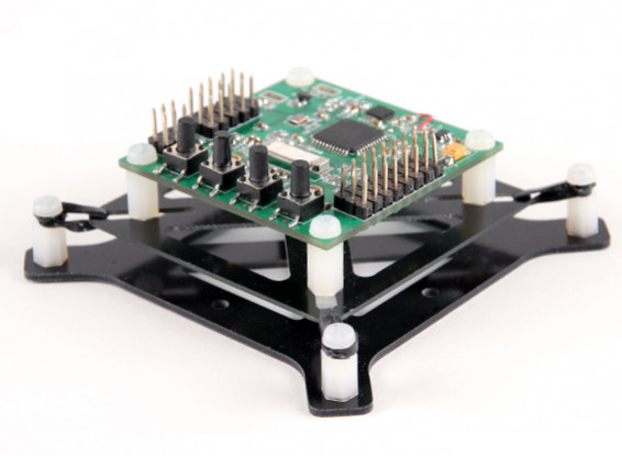
One simple way to address mechanical shock and vibration alongside potential electrical/thermal factors is to use a shock-mounting with a vibration damper. The damper shown below is hobby-grade, but it has a very similar structure to the mounts used in quadcopter drones.

Other aspects of enclosure design and mounting will need to consider the specific environmental factor you need to address. Accommodating an environment with a high pressure gas will not use the same strategy that is used in a high pressure liquid environment, even though both of these are enclosure-level solutions that rely on pressure equalization. Rugged electronics design is a great example where the electrical design team needs to closely communicate with the mechanical team to ensure the ruggedization strategy does not interfere with electrical requirements.
Final Thoughts on Rugged Electronics
The last piece of advice I can give around rugged electronics is that you won’t won’t always be deploying a device in a scenario that comprises the entire list of harsh environments. Therefore, the first step in designing rugged electronics is to consider the specific environmental factors that could damage the product and focus on these in your design. For example, don’t worry about designing protection from oxidizing gases if your chief worry is temperature cycling (although you might get this protection as a side benefit). Focus on what matters for your design and you can still produce something that is compact and cost-effective.
With the best PCB design tools in Altium Designer®, you can design high-quality rugged electronics, including your enclosure and fabrication data. For enclosure design, you can use the MCAD CoDesigner extension to easily import your board into Autodesk Inventor, Solidworks, or PTC Creo. When you’ve finished your design, and you want to release files to your manufacturer, the Altium 365™ platform makes it easy to collaborate and share your projects.
We have only scratched the surface of what’s possible with Altium Designer on Altium 365. Start your free trial of Altium Designer + Altium 365 today.
