Using SPICE as a MOSFET Power Dissipation Calculator
Circuit diagrams and schematics form the core of your PCB design, and reliability requires that you calculate the power dissipation in your circuits. Some components, like MOSFETs, have clearly defined electrical ratings, but determining whether your design will comply with these ratings is not such a simple problem. Calculating power dissipation in active components, some semiconductors, and MOSFETs takes SPICE packages that implement real component models.
For designers who need a MOSFET power dissipation calculator, an easy-to-use SPICE simulation package can be used to quickly calculate the power dissipated in a MOSFET. Altium Designer’s updated SPICE simulation engine can help you quickly create MOSFET circuits and analyze the power dissipation to ensure design reliability. You’ll also have access to a comprehensive PCB layout editor to help you prepare a real board for production.
ALTIUM DESIGNER®
The best electronics design software with advanced CAD tools for design professionals.
Finding reliable utilities to calculate circuit behavior in active devices can be difficult. Some circuits cannot be analyzed using standard circuit techniques as the problems involve complex transcendental equations, requiring an iterative numerical algorithm to solve. In problems like these, simulation tools need to be used inside your circuit design software to help you evaluate design reliability.
Some common circuits that need to be evaluated for reliability are MOSFET circuits, specifically power MOSFETs and amplifiers. These circuits are ubiquitous as MOSFETs have replaced BJTs in many applications operating at high power and high frequency. As these components can run at high power and can reach high temperature during operation, designers might start looking for a MOSFET power dissipation calculator to ensure design reliability.
While there is no simple calculator application that can help you ensure reliable operation of your MOSFET circuits, Altium Designer includes everything you need to design and simulate MOSFET circuits so that you can ensure reliable power delivery with your components. Keep reading to see what you can design in Altium Designer and how you can simulate your MOSFET power distribution.
Using SPICE as a MOSFET Power Dissipation Calculator
To run a simple simulation for MOSFET power dissipation, you must first use a circuit editor or a schematic creation software application to build your MOSFET circuit. The best software will give you access to a comprehensive component library so you can build your circuits and simulations. The example image below shows a simple MOSFET amplifier circuit connected to a high impedance load. This circuit was built in Altium Designer and can be easily simulated with a basic SPICE package.
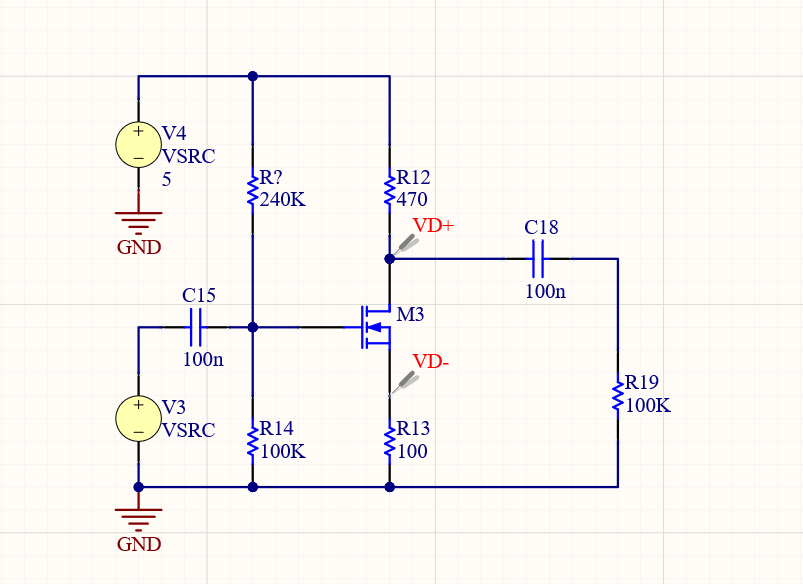
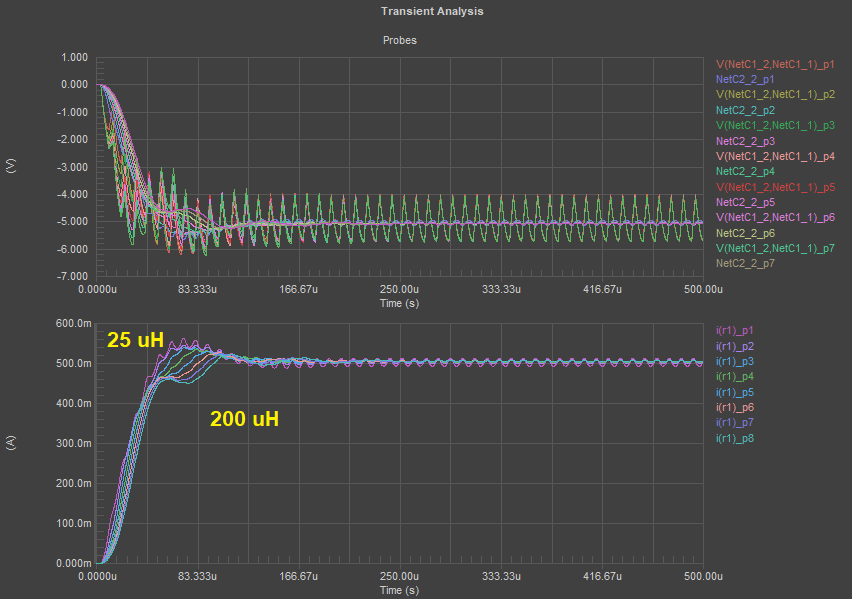
In this circuit, you can run a transient analysis simulation to examine how the circuit comes to its steady state. This simple circuit is part of a larger system, but it can be easily simulated in isolation to determine the power output. The power output is found by multiplying the voltage differential (measured with the probes in the above image) and the current through resistor R13.
Because the schematic editor in Altium Designer gives access to component libraries with generic simulation components, it only takes a few minutes to set up the above circuit and start running simulations. The schematic editor includes a SPICE simulation package with a simplified interface, allowing you to access the standard set of simulations you need to analyze any circuit. You aren’t limited to generic simulation components in your design, you can assign SPICE subcircuit models to your components so you can better predict and model the electrical behavior of your design.
More Advanced Simulations in Altium Designer
While transient power calculations in Altium Designer are useful, they aren’t the only simulations you can perform. Any SPICE simulation for your MOSFET circuits can be performed in Altium Designer’s schematic editor. Instead of using separate schematic sheet creation tools and circuit simulators, use the complete set of design tools in Altium Designer. Schematics, circuit diagrams, simulations, and ultimately a PCB layout are accessible together in Altium Designer.
- Your MOSFET power dissipation calculation starts with creating schematic sheets with your circuit diagrams.
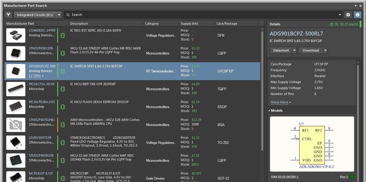
Learn more about creating schematics in Altium Designer. - The Manufacturer Part Search panel helps you search through the electronics supply chain and find real components with verified PCB footprints for your schematic design.
Learn more about the Manufacturer Part Search Panel in Altium Designer. - If you’re not familiar with SPICE simulations, we’ve compiled the essential information you need to know to be successful with this standard simulation package.
Learn more about SPICE simulations in Altium Designer.
Build and Simulate More Complex MOSFET Circuits
The primary goal of using a MOSFET power dissipation calculator is to ensure your MOSFETs aren’t dissipating so much heat that they overheat and fail. Overheating during DC operation and high transient current draw during switching, followed by fast overheating, are the most common causes of MOSFET failure. To prevent excessive current draw, power dissipation, and overheating, MOSFET circuits can get more complex.
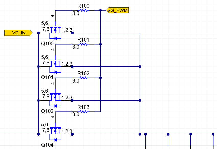
One option is to put MOSFETs in parallel so that they can still provide the required current in a system. By placing MOSFETs in parallel, the total power dissipation is split between the MOSFETs in the array. This arrangement requires simulation to ensure the circuit will not produce unwanted oscillations or overcurrent during switching. SPICE simulations with real component models can still be used to examine these more complex MOSFET circuits, as well as other circuits in your design.
Hierarchical Schematics Can Help You Stay Organized
Altium Designer’s schematic editor allows you to create a hierarchical structure for your project to help you organize your circuits and stay productive. Designers can implement flat, hierarchical, or multichannel design structures so that more complex circuits can be created and simulated. Once you’ve captured your schematics and assigned CAD data to your components, you’re ready to import your design into a new PCB layout.
- A hierarchical project structure helps you stay organized and build complex PCBs.
Learn more about the advantages of hierarchical schematic design. - Parallel MOSFETs are often used in power converters and motor control systems that require high current.
Learn more about using parallel MOSFETs in your power and motor control systems. - Altium Designer’s powerful schematic editor gives you the tools you need to design high power systems with MOSFETs for a range of applications, such as lighting systems.
Learn more about designing power systems with high power MOSFET circuits.
Easily Transition to Your PCB Layout
Once you complete your circuit board schematics, you’re ready to import your components into your PCB layout and you can begin arranging your components in your circuit board layout. Altium Designer includes a complete set of CAD tools in an integrated PCB layout editor so you can quickly import and arrange your components in your circuit board. While other circuit board design platforms separate your design features into different applications, Altium Designer gives you access to everything you need in one application with a single workflow.
Complete Circuit Design and PCB Layout in Altium Designer
Only Altium Designer includes everything needed to create and simulate your MOSFET circuits, followed by creating your PCB layout and routing your board. When you’re ready to produce your board, you can quickly generate PCB manufacturing files from your circuit board layout data with Altium Designer. Use the OutJob file to take your PCB data and generate standard deliverables needed by a PCB manufacturer.
- Altium Designer gives you everything needed to turn your ideas into reality. You can build anything from simple MOSFET circuits to advanced electronics in Altium Designer.
Learn more about Altium Designer‘s integrated PCB design tools. - The power of Altium Designer’s user interface comes from an integrated design rules engine that lets your design features work together in a single program.
Learn more about the PCB design interface in Altium Designer. - All Altium Designer users can share their designs through the Altium 365 platform. Design teams use Altium 365 to stay productive and share design data in a secure cloud environment.
Learn more about sharing your PCB design data on Altium 365.
The schematic editor and SPICE simulation package in Altium Designer can give you everything you’d expect to find in a MOSFET power dissipation calculator. When you need a complete set of component creation and management tools, use the industry’s best ECAD utilities for creating and simulating your circuits.
Altium Designer on Altium 365 delivers an unprecedented amount of integration to the electronics industry until now relegated to the world of software development, allowing designers to work from home and reach unprecedented levels of efficiency.
We have only scratched the surface of what is possible to do with Altium Designer on Altium 365. You can check the product page for a more in-depth feature description or one of the On-Demand Webinars.
