What is SPICE Simulation in Electronics Design?

Electronics veterans probably know quite a bit about SPICE simulations, but even some old-school engineers still run off their intuition and experience when designing circuits. SPICE simulations are probably the most famous simulation tool used in electronics design, whether for PCB design, integrated circuit design, or for designing other electrical systems. But at a deeper level, what is a SPICE simulation, how does a SPICE simulation work, and what are some best practices for using SPICE?
If you’re new to SPICE simulations and you’ve never used a simulator as a PCB designer, then don’t fret. You don’t need to be an expert on electrical simulations, but knowing how to use a SPICE simulator and how to interpret the results helps you design accurately for many applications. Keep on reading to learn about what is a SPICE simulation and how to use them in your designs.
What is a SPICE Simulation?
The acronym “SPICE” stands for Simulation Program with Integrated Circuit Emphasis, although this simulation framework can be used for much more than just integrated circuit design. The original Berkeley SPICE simulation application was released as open source, and it forms the basis of today’s SPICE simulation applications. A SPICE simulation application can be used to simulate the electrical behavior of many analog or mixed signal circuits. Many digital simulation tasks can be performed in basic SPICE simulation applications, and more specialized SPICE simulators can run logic simulations for digital circuits.
There are a few basic analyses that can be performed in typical SPICE simulation applications. These tasks include:
- DC sweep: This is a basic time-independent simulation, where the DC current in a circuit is calculated as a function of DC input voltage. The input voltage is swept and the results are displayed on a graph.
- Transient analysis: This is a fundamental application for simulating AC circuits, including circuits with nonlinear components and arbitrary waveforms. Results are displayed in the time-domain.
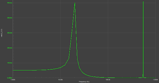
- Frequency sweep: A frequency sweep is the conjugate simulation to transient analysis. This involves calculating the circuit response in the frequency domain, such as you might do with a filter or impedance matching network.
- Parameter sweep: A parameter in the circuit can be swept through some values as part of another simulation. This is often used to experiment with different component values and see how they affect electrical behavior.
Aside from these fundamental analyses, different commercial SPICE applications include different features, user interface, and commands. Various SPICE simulators found in commercial applications or as open source programs online will have their own prefixes or suffixes (e.g., HSpice, LTSpice, etc.). Although the programs themselves may be very different in terms of user experience and features, they all rely on the same fundamental algorithm for solving circuit analysis problems.
SPICE Solution Algorithm
The primary solution technique used in SPICE is nodal analysis. The nodal analysis technique returns a linear system of equations (written as a matrix) and solves this system using matrix arithmetic. While this algorithm can be implemented by hand for simple circuits, it quickly becomes an intractable problem in large circuits. Imagine a circuit with 100+ components and a similar number of nets; you would have to solve a massive matrix equation to determine the voltage and current in such a circuit.
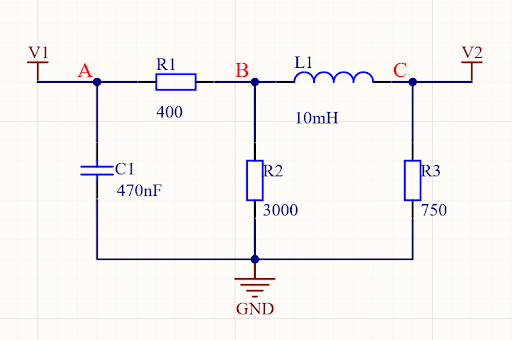
In deriving the matrix equation for a given circuit, nodal analysis requires defining nodes in a circuit diagram, and a set of linear equations is derived for the voltage drop across each component. In the image below, we have 3 nodes (labeled A, B, and C) and GND as a reference node. By “reference node” in nodal analysis, we mean that the voltage measured “at a node” is measured with respect to GND. You can actually have multiple reference nodes, which is equivalent to having multiple galvanically isolated grounds at different potentials.
Matrix Equation
In the above circuit, the matrix equation has a general form that is a function of the voltage drops between adjacent nodes. In other words, we can write an equation that is a function of voltage differences between nodes (assuming GND is used as the reference node) and the set of input voltages:
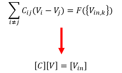
The voltages (V) that need to be calculated in this matrix equation can be in the frequency domain, or they can be time-dependent. By iterating this equation for different times and frequencies, the voltage and current at each node can be calculated. Again, you could do this by hand, but an integrated SPICE simulator automates this tedious process.
Once you’ve got a matrix equation in this form, a technique known as the Gauss-Jordan method is normally used to reduce these equations to the point where they can be solved iteratively. You can look online for the details of this method if you want to code it yourself. However, a SPICE simulator can do the repetitive calculations in the Gauss-Jordan method very efficiently.
Stay Productive With an Integrated SPICE Simulator
If you’re a PCB designer, you’ve probably focused a lot more on routing than on simulation. However, today’s PCB layout designers also need to play the role of electrical engineers, meaning they’re likely to spend time designing circuits, and they’ll need to run simulations of their circuits to ensure proper functionality. Today’s designers even need to do other tasks like firmware development, manufacturing preparation, sourcing, and mechanical design.
The best PCB design applications will integrate your SPICE simulation tools, PCB layout features, and everything else you need into a single application. Once you know what is a SPICE simulation, you can use the complete set of design tools in Altium Designer® to design and simulate all aspects of your circuits. You can then import your components into a blank PCB layout without using an external schematic capture utility. Take control over all aspects of your PCB with the industry’s best design tools in Altium Designer.
When you’ve finished your design, and you want to share your project, the Altium 365™ platform makes it easy to collaborate with other designers. We have only scratched the surface of what is possible to do with Altium Designer on Altium 365. You can check the product page for a more in-depth feature description or one of the On-Demand Webinars.
