NTC Thermistors as Temperature Sensors
In the introduction to this series, we started work on testing all the different types of temperature available by building a set of project templates: one for analog sensors and one for digital sensors. You can find those templates and the sensor implementations for these NTC thermistors on GitHub. As always, these projects are open source, released under the MIT license allowing you to use them with very little in the way of restrictions.
In this article, we’ll be starting with our first type of temperature sensor, the negative temperature coefficient (NTC) thermistor. NTC thermistors are probably the most commonly used class of sensor as they are cheap, easy to use, and despite not being incredibly precise are accurate enough for most applications.
If you're looking to purchase NTC thermistors, head over to Octopart and see what's in stock with your favorite distributor. You can also find a full range of NTC thermistors, and many tens of thousands of other components and sensors, in my Celestial Altium Library, the largest open source library for Altium Designer®.
In this series, we’re going to be taking a look at a wide range of temperature sensors, talking about their advantages and disadvantages as well as common implementations/topologies for their implementation. The series will be covering:
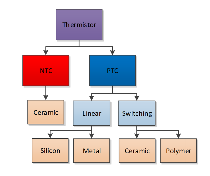
- Negative Temperature Coefficient (NTC) thermistors
- Positive Temperature Coefficient (PTC) thermistors
- Resistance Temperature Detectors (RTD)
- Analog Temperature Sensor ICs
- Digital Temperature Sensor ICs
- Thermocouples
Sensing with Thermistors
Despite what I’ve just said about thermistors not being particularly precise, they are widely used. Most applications don’t need better than a few degrees Celsius of temperature precision. When building in basic thermal protection or thermal compensation, PTC or NTC thermistors are good enough. Most 3D printers use thermistors for their heated beds and hot ends, which is why you need to calibrate your filament temperature settings for every printer. For me, printing the same material with three different hot ends, I have three temperatures over a span of almost 10 °C. The sensors are very cheap to use, which is fantastic for low-cost devices, especially where you can either calibrate the sensor in a circuit at the time of manufacture, or the user can.
The cost of thermistors is offset by the extra engineering effort to obtain an accurate temperature measurement, especially over a wide range of temperatures. This makes them very good for protection applications where a general idea of temperature is acceptable. Most lithium-ion battery packs will implement a 10k NTC thermistor to shut off charging if the cells are getting too hot in order to prevent a catastrophic failure.
Negative Temperature Coefficient (NTC) Thermistors
An NTC Thermistor is a resistor in which the resistance drops as the temperature increases. This allows typical methods of measuring resistance in a circuit to calculate the temperature of the resistor. Unfortunately, the temperature change is non-linear, which means you cannot directly measure temperature change by the change in resistance. Many manufacturers will provide a resistance-temperature curve and perhaps even a formula to calculate the temperature from the resistance, which means a microcontroller can be used to gain a reasonably accurate measurement. Suppose the manufacturer does not provide this information. In that case, you can use a precise temperature sensor or environmental chamber to measure the sensor at specific set points to determine the formula yourself.
In this project, we’re going to look at two different NTC thermistors and several implementations for them. These are tight tolerance thermistors, but they are still not excessively expensive compared to other lower tolerance thermistors.
Both of these are surface mount components; however, through-hole components are readily available. A common application of the through-hole components is to solder them to the end of a pair of wires for remote sensing. If you want to test a thermistor on a wire without spending much money, search for 3D printer temperature sensors, they will typically be a 10K thermistor. However, some printers do use 100K thermistors instead.
|
Part |
NCP03WF104F05RL |
NCP15XH103F03RC |
|
Sensing Temp Min |
-40°C |
-40°C |
|
Sensing Temp Max |
+125°C |
+125°C |
|
Sensing Range |
Local |
Local |
|
Resistance at 25°C |
100 kOhm |
10 kOhm |
|
Resistance Tolerance |
1% |
1% |
|
B Value Tolerance |
1% |
1% |
|
Operating Temperature |
-40 °C to +125 °C |
-40 °C to +125 °C |
|
B0/50 |
- |
- |
|
B15/75 |
4250K |
3380K |
|
B25/75 |
- |
- |
|
B25/85 |
4311K |
3434K |
|
B25/100 |
4334K |
3455K |
|
Max Power (mW) |
100 mW |
100 mW |
|
Manufacturer |
Murata |
Murata |
|
Package |
0201 |
0402 |
The sensing temperature range of thermistors is an advantage over some of the sensors we’ll look at later. The sensing range covered the full operating range of the sensor, allowing it to be used in a wide variety of applications. As thermistors are so simple, you can use them well beyond these rated ranges too as long as your solder doesn’t turn to a molten state, or thermal contraction does not damage the device.
The primary difference between the two sensors, other than package size, is the resistance at 25 °C - we have a 100k and 10k NTC thermistor, which are the most commonly used values.
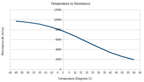
The datasheets for these two sensors do look fairly linear until you realise that the resistance axis is logarithmic. On a linear scale, like the graph below, we can see that the resistance is far from linear when read directly.
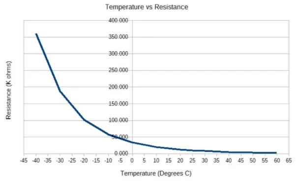
We can place a resistor that matches the resistance of the thermistor at the centre of the temperature range of interest in parallel with the thermistor to make a small section of the curve more linear. This can make for a more straightforward calculation and calibration within the linear temperature region. Suppose you have the capability to measure a thermistor’s full profile to calculate the values for the thermistor formula, or the manufacturer is kind enough to supply them in the datasheet. In that case, you can save a resistor and still have an accurate measurement across the full range.
NTC Thermistor Implementation: Voltage Divider
The most straightforward way we can measure the temperature is with a voltage divider. You can use the thermistor as either the top or the bottom leg of the potential divider. If you use the thermistor as the “top” leg of the potential divider, the voltage will increase as the temperature increases. If you use a thermistor as the bottom leg of the voltage divider, then the voltage will decrease as the temperature increases.
Either method is valid. However, I would suggest trying to reduce the current through the divider in order to prevent self-heating of the thermistor. Depending on your NTC thermistor value and requirements, you may be able to optimise the implementation by changing the topology.

For my implementation, I’m using a simple divider that is not optimised for any particular temperature range by using an upper divider that matches the resistance of the thermistor at 25 °C. At 25 °C, we should expect half the input voltage. Suppose you were building a temperature sensor in this way. In that case, you should have an understanding of the temperature range you are working with and optimise the resistance and topology to provide the widest possible range of voltage to be able to measure the temperature more accurately.
Note that, as the temperature goes up, the resistance of the NTC thermistor will go down. This means that the majority of power will be dropped across the reference resistor since it has the larger voltage drop. This also helps prevent self-heating and is a good strategy if we want to measure temperatures above ambient.
PCB Layout
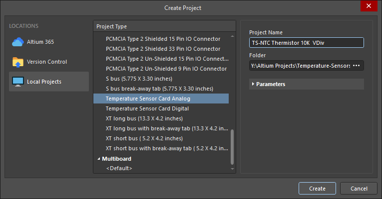
To create the PCB, we’re going to use the Temperature Sensor Card project template we created in the previous article in the series. The template is also available on GitHub if you’d like to use it for your own sensors.
One thing you might notice is that the board names are the same as they are in the project template. This is not going to make managing potentially dozens of these boards easy if they are all going to have the same schematic and PCB file names!
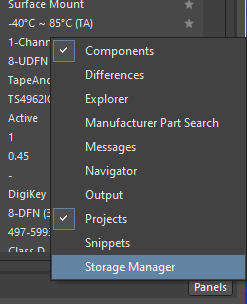
I asked my friend Davide Bortolami if he had a way to rename files in an Altium project since my practice was to remove the file from the project - rename it, then add it back to the project again. My way was pretty clunky, so Davide immediately suggested the Storage Manager for renaming the files. You can find the storage manager under the panels button in the bottom right of Altium.
The storage manager works just fine even if you don’t have your current project in a version control repository. All we need to do is right click on the schematic or PCB and click Rename (or press F2).
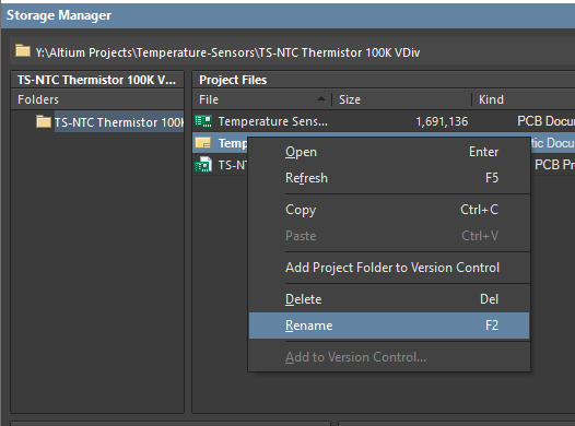
This is a much more elegant solution than the method I would typically have used.
We then add one of the implementations from above to the schematic sheet. The only change needed to the templated sections of the schematic is to connect the sensor’s analog output to the card edge connector.
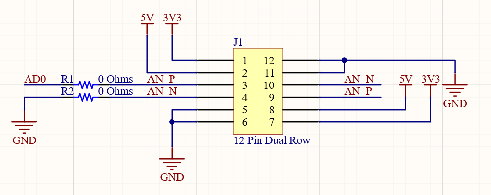
As these schematics are single-ended, and not differential, we can connect the negative side of the pair to ground, with the positive side getting the output from the voltage divider connected to it. Then all we need to do is update the board to add the new components.
While working on the board, I’m also filling in the analog channels table we placed in the template to identify which channel the particular sensor card is using. This should reduce the chance of adding two sensors using the same channel to a single stack.
.png)
The boards for these are of course unbelievably simple, with just two components added per board. I could have placed both sensors on the same board, but I want to keep it to one sensor per board. By keeping each sensor implementation isolated to its own circuit board, no sensor will influence the results from any other because they share a board.
.png)
The 100k NTC thermistor board is essentially identical to other than the resistor and thermistor components. The project template prepares easy work of creating a series of very similar circuit boards.
.png)
NTC Implementation: Adding a Parallel Resistor
As mentioned above, we can add a resistor in parallel to the NTC thermistor in our voltage divider. This will help linearise a section of the voltage divider. Having a linear output for the temperature range of interest can be useful if you cannot run an algorithm on the collected data to convert the value to a precise temperature. It can also be helpful if you do not have the facilities to precisely collect the necessary data to determine the values for the algorithm. The linear section of the temperature range will need a voltage reading, which can be interpreted as differential temperature directly.
.png)
For this implementation, I’m simply adding a parallel resistor that will linearise the thermistor around 25 °C. Your implementation should match the resistance of the NTC thermistor at the centre point of the temperature range you are trying to measure.
I have placed the two 10K 0603 resistors together for this implementation, as I don’t expect there to be any measurable difference in the physical position of the parallel resistor to the thermistor. If we had precise enough instrumentation, we could likely sense some heat from the parallel resistor heating the thermistor if they were close together. Still, it would be such a vanishingly small amount that it would make no difference to any real-world application.
.png)
NTC Implementation: Adding a Voltage Follower
For improved stability of the circuit, we can also use an op-amp as a voltage follower. This can also give us a little extra precision depending on how the pin that is measuring the voltage is implemented. A microcontroller or dedicated ADC will have some resistance to ground, which is typically very high, but it will still act as a parallel resistor to our voltage divider. By using a buffer/voltage follower op-amp, we can isolate the microcontroller pin from the voltage divider.
.png)
I’m using a relatively low-cost buffer amplifier for this circuit. An instrumentation amplifier would be a similar cost. It’s worth noting that some of the analog and digital sensors we look at later on in the series cost less than just the buffer amplifier and have greater precision and linearity than a PTC or NTC thermistor. So while this circuit should provide a more accurate reading, it probably wouldn’t make much sense in an actual device implementation unless you are reading a thermistor from an external device/machinery where you can’t change the sensing element.
You could also use a general-purpose operational amplifier for this, with a reduced cost. Buffer amps have a gain of one, so there is no feedback connection required - and more importantly, have an exceptionally high input and output impedance. This high impedance compared to a regular operational amplifier offers greater accuracy when reading a voltage divider such as this. That being said, a buffer amp like this is massive overkill for an NTC thermistor, as it’s more than capable of handling GHz signals.
The PCB for the voltage follower implementation follows the same overall style of the others, with the buffer amp and divider resistor on the opposite side of the thermal break. Again, I would not expect there to be any measurable heat from the buffer amplifier being conducted to the thermistor if they were placed together. This design continues with the theme of keeping only the sensing element inside the thermal break area so all our measurements will be consistent and not biased by other components nearby.
.png)
Other Options: Wheatstone Bridge
You could also use a Wheatstone bridge for an even more precise measurement of the thermistor. However, I’m not going to implement it for an NTC thermistor in this series. In the Resistance Temperature Detector (RTD) article, you will find more about implementing a Wheatstone bridge. While a thermistor implemented correctly and used with the correct formula can be quite precise, using a Wheatstone bridge on a relatively inaccurate sensor isn’t worth the implementation time and cost. The results from the simple applications above are going to allow you to get the most from an NTC thermistor.
Test the NTC Thermistor Boards Yourself
These sensor test cards are open source, check out the repository on GitHub to download the designs and use them yourself. If you’re looking to evaluate some NTC thermistors, the project files for these boards will save you time. You’ll also find all the sensor cards we develop during this series in the same GitHub repository, so you might be able to get a sneak peek at what is coming up next in the series by checking the repository!
Would you like to find out more about how Altium can help you with your next PCB design? Talk to an expert at Altium.