Temperature Sensor Project: Analog Temperature Sensor ICs

In this article, we’re looking at the fourth class of temperature sensors in a series of articles that are all about measuring temperature. In the introduction, we created a set of project templates that will allow us to develop stackable, analog, or digital sensor cards for testing different types of temperature sensors. At the end of the series, we’ll be building a set of host boards for these, which will allow us to compare the performance and accuracy of not only the different sensor types but also the various implementations for these sensors.
In this series, we’re going to be taking a look at a wide range of temperature sensors. We will be talking about their advantages and disadvantages as well as common topologies for their implementation. The series will cover:
- Negative Temperature Coefficient (NTC) thermistors
- Positive Temperature Coefficient (PTC) thermistors
- Resistance Temperature Detectors (RTD)
- Analog Temperature Sensor ICs
- Digital Temperature Sensor ICs
- Thermocouples
Today we’re looking at analog temperature sensor integrated circuits - we’ll only have one implementation per circuit, unlike in the previous articles. These integrated circuits take care of all the linearization and amplification that we’ve had to take care of ourselves when using a resistive element for temperature sensing. These sensors may internally have a range of different topologies and sensor types, but their internal implementation doesn’t matter to us. They all provide a relatively linear output that is well suited for direct use with a microcontroller analog to digital converter (ADC) or analog circuitry.
With a small number of supporting components required, their high precision, and convenient output voltage, you might think that using an analog sensor IC is going to be substantially more expensive than implementing your own using one of the discrete sensing elements we’ve already looked at. Generally, the opposite is true. You can typically add an analog temperature sensor IC to your circuit for a lower cost than all but the most basic implementations of a discrete component-based temperature sensor, and the output will be far more precise and linear.
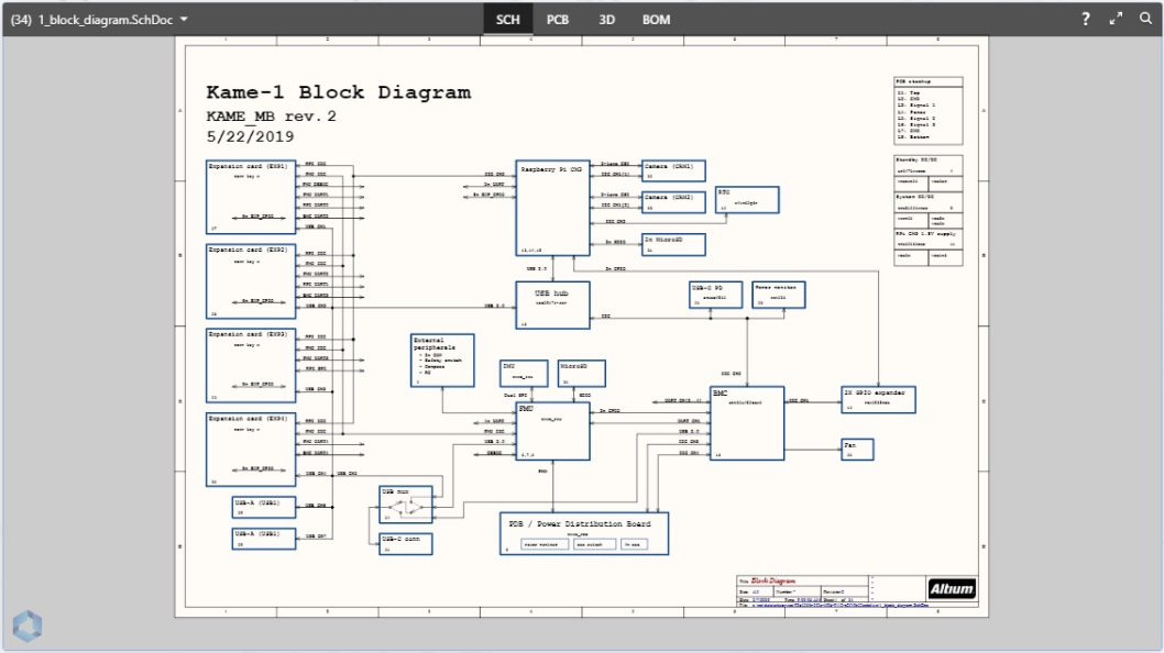
As with all my projects, you can find the details of the project, the schematics, and the board files on GitHub along with the other temperature sensor implementations. The project is released under the open-source MIT license, which allows you to use the designs or any part of them for personal or commercial purposes, as you wish.
Above is the PCB design you'll be reading about in the Altium 365 Viewer, a free way to connect with your co-workers, clients, and friends with the ability to view the design or download with the single click of a button! Upload your design in a matter of seconds and have an interactive way to take an in-depth look without any bulky software or computer power.
Analog Temperature Sensor ICs
With the many implementation options of the previous sensor types we looked at in the preceding articles, you may be thinking by this point that sensing temperature is a lot of hard work when using passive components. If you just want a simple linear voltage that correlates closely with temperature, then you might be best off looking at an analog temperature sensor. The analog voltage allows you to sample the temperature using a microcontroller ADC pin. Alternatively, you can use the output to feed other analog circuitry such as a comparator to provide temperature control or safety features without needing to use a microcontroller or other digital device.
Internally, these sensors will typically work pretty similarly to the passive components we have previously looked at. However, they have built-in compensation to linearize their outputs. When the output is less than perfectly linear, the datasheet will typically include a formula to allow the precise conversion of the voltage to temperature without needing to lab test the sensor to determine the compensation variables. This greatly simplifies the engineering process compared with qualifying a circuit built using a resistive element and operational or instrumentation amplifiers.
Despite this convenience, analog integrated circuit temperature sensors are cheaper than the passive components we’ve looked at with comparable levels of accuracy/precision, for the cost of any implementation other than a voltage divider, you could buy an analog sensor. The sensing temperature ranges of the ICs are more limited than for an RTD, but they are similar to the advertised range for a thermistor. The silicon in the sensors and the fact that they tend to be soldered onto a board or wires will be the limiting factor for the maximum temperature, yet despite this, the min and max sensing range can typically fall between -55°C and 150°C. This temperature range should be sufficient for the vast majority of projects that need to sense the environmental conditions in a location where other electronic devices are operating.
For this project, we’ll take a look at three different sensors that have a variety of operating temperatures and precisions along with a wide input voltage range.
|
Name |
LMT87DCKT |
LM62 |
MAX6605MXK |
|
Type |
Analog |
Analog |
Analog |
|
aSensing Temp Min (°C) |
-50°C |
0°C |
-55°C |
|
Sensing Temp Max (°C) |
+150°C |
+90°C |
+125°C |
|
Accuracy (°C) |
±0.4°C (±2.7°C Max) |
±3°C |
±3°C (±5.8°C) |
|
Sensing Range |
Local |
Local |
Local |
|
Resolution/Sensor Gain (mV/°C) |
13.6 mV/°C |
15.6 mV/°C |
11.9 mV/°C |
|
Operating Temp (°C) |
-50°C to +150°C |
0°C to +90°C |
-55°C to +125°C |
|
Min Supply Voltage (V) |
2.7 V |
2.7 V |
2.7 V |
|
Max Supply Voltage (V) |
5.5 V |
10 V |
5.5 V |
|
Current Consumption (uA) |
5.4 ~ 8.8 uA |
~130 uA |
4.5 ~ 10 uA |
|
Manufacturer |
TI |
TI |
Maxim integrated |
|
Package |
SC-70-5 |
SOT-23-3 |
SC-70-5 |
These devices were chosen to demonstrate a wide range of price and performance points. In the final article in this series, we’ll be taking them beyond their operating temperature ratings to see how they respond across their full sensing range and beyond.
Analog Sensor Implementation: Texas Instruments LMT87DCKT
The LMT87 from Texas Instruments is a small SC-70 sized CMOS temperature sensor. Out of all the analog sensors we’re investigating for this project, the LMT87 has the highest typical accuracy of 0.4%. However, even the worst-case accuracy of +/- 2.7°C is still ahead of the other sensors. While it’s quiescent current is also lower than the others, at least when using a 2.7 V supply, it also has a power-on time of just 0.7 milliseconds. This makes it even more power-efficient if you cycle the power to it just before taking a temperature measurement, which makes it the ideal sensor for low power/power-constrained applications. With the very low power consumption of the device, it can be powered directly from a microcontroller or other logic device without needing to worry about exceeding the maximum ratings for the IO pin. For lower voltage applications, there are further options in the LMT8x series of devices that support operating with supplies down to 1.5 V, however, with a reduced gain to go with the reduced supply voltage range.
It’s worth noting that the LMT87 is also available in an automotive-qualified variant as well, which may be useful for some users.
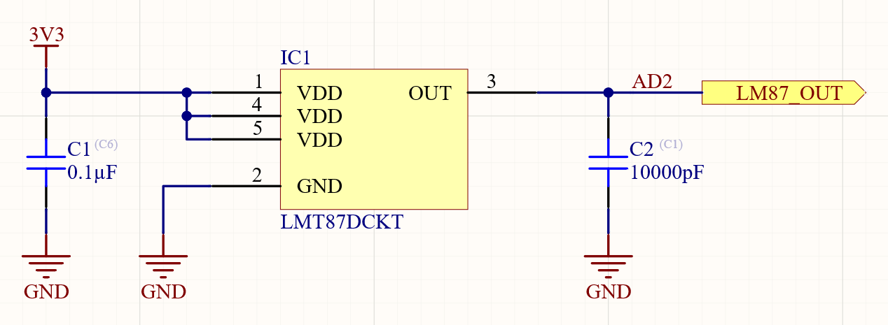
For the implementation of this sensor, I’m adding a decoupling capacitor and an output capacitor. The datasheet specifies that neither is required; however, we want to allow this sensor to have the best opportunity to shine in our testing. The output capacitor is not strictly needed, but it enables a SAR to ADC to draw bursts of current as it samples. It does this without negatively affecting the reading should the temperature sensor be unable to supply the required instantaneous current to keep the output voltage where it should be for the temperature reading. Both capacitors part numbers are already being used for other projects in this series, so these will not significantly add to the total cost or the number of components that need to be ordered.
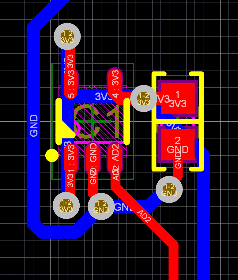
The datasheet kindly provides a suggested layout for the surface mount variant of the component that we are using; however, I have deviated from it slightly. Where the datasheet suggests connecting to ground and power planes, I’m connecting to traces instead. I don’t really want to add a ground pour on the bottom layer, as it could influence the results of the temperature tests/comparisons that we’ll perform later in the series. By having a ground pour, with its thermal mass/conductivity, present under the LMT87 sensor but not under any of the other sensing elements that we are using, it could affect results. It won’t, therefore, accurately demonstrate the sensor performance.
In the 3D view, you can see that I’ve positioned the sensor in the same position as the other designs we’ve worked on previously in this series of articles. I have placed the power supply decoupling capacitor next to the IC. However, I have placed the decoupling capacitor for the analog output next to the connector, where it can do the most good.
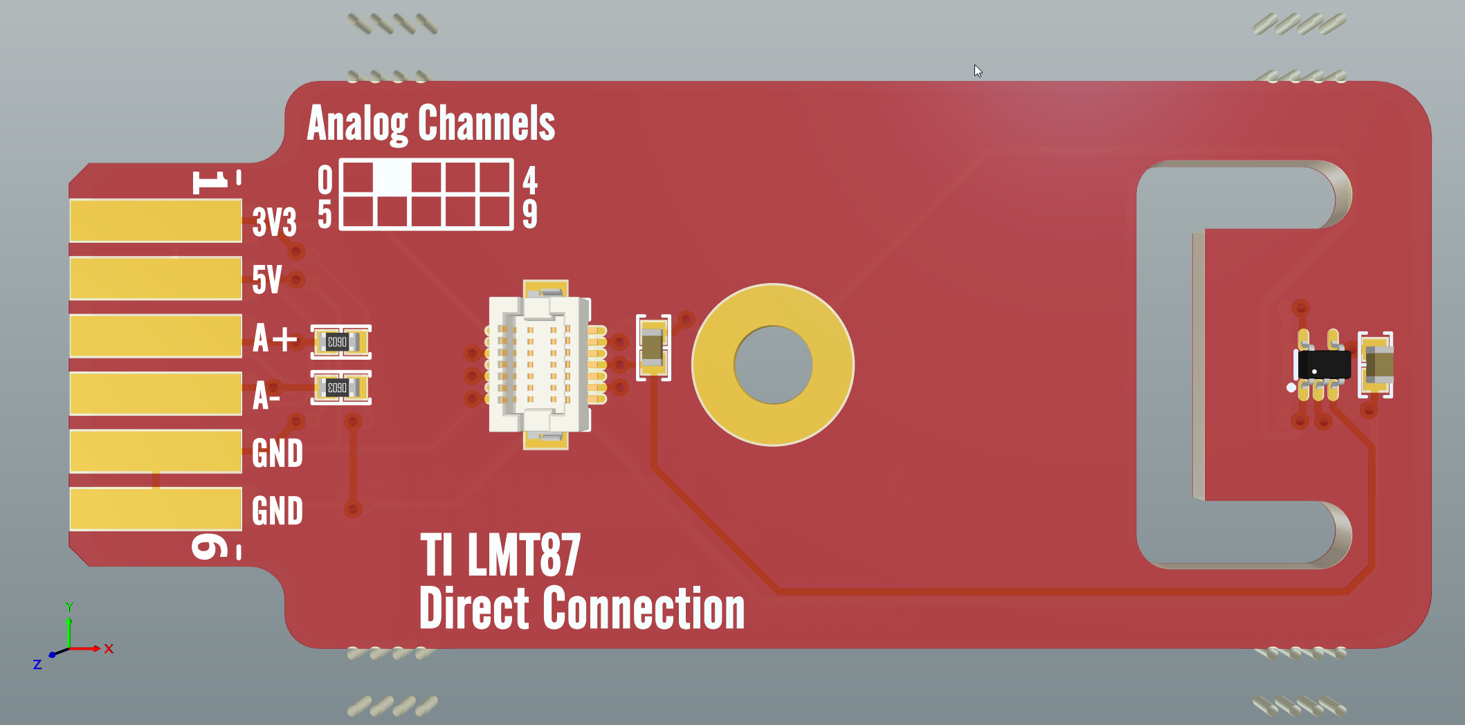
The board shape and connections are all provided by the project/board template we created in part one of this series, Temperature Sensor Project: Intro.
Analog Sensor Implementation: Texas Instruments LM62
The Texas Instruments LM62 has been around since the end of the 90s and yet is still relevant today. While it’s accuracy and sensing range isn’t as good as other sensors, it’s still a highly practical sensor for many applications. The LMT87 we looked at above is more accurate, draws a lower current, and is much more modern than the LM62, while also being available at a lower cost - so why include the LM62 in this list? I thought it would be interesting for this exercise to include a component that is still relatively common and yet has the drawbacks of a measurable self-heating effect and a limited temperature sensing range.
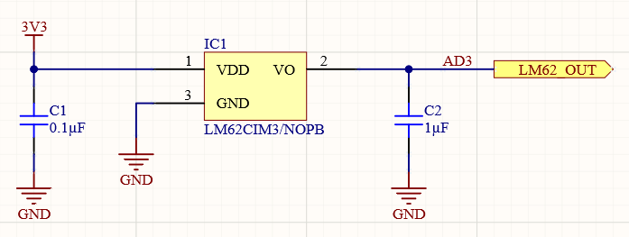
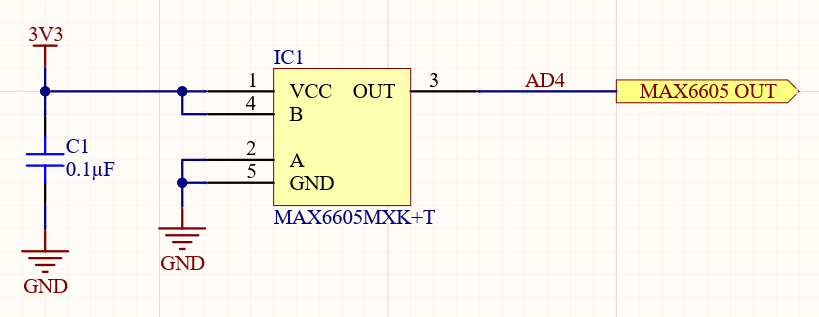
The LM62 does have some advantages, though, such as greater sensor gain at 15.6 mV/°C and an operating voltage range that extends up to 10 V. Furthermore, with the limited temperature range, the output voltage at its maximum sensing temperature of 90°C is 1.884 V. This enables an additional gain to be applied using an operational amplifier or instrumentation amplifier. This provides an even higher gain across the full sensing range if you are using a 3.3 V microcontroller or a full sensing range that is within the capabilities of a lower voltage logic device.
The LM62 also has excellent linearity over its sensing temperature range, with the maximum deviation being just 0.8°C.
As with the LMT87, the LM62 is capable of being powered from an IO pin of any microcontroller or logic device; while its current consumption is significantly higher, it is still a small fraction of the power that a microcontroller pin can supply.
As with the LMT87 above, I’m implementing the optional capacitors for the LM62. The LM62 does not need a decoupling capacitor fitted on the input or output; however, the datasheet does have a suggestion for a filter for use in noisy environments. The evaluation boards that we build will not actually be situated in an electromagnetically noisy environment. However, the response time of the LM62 is significantly slower than the time constant of the RC filter at the output, formed by the 1 uF capacitor. As a result, the overall response of the LM62 will not be significantly affected.
I mentioned at the start of this article that you might prefer using an analog sensor rather than a digital as it can be more convenient for building into analog control circuitry. Since we’re talking about implementation options and datasheet recommendations - the datasheet for the LM62 has a nice thermostat example, which could have many applications in control circuitry, even just to switch on a fan or a heater without needing a microcontroller’s intervention.
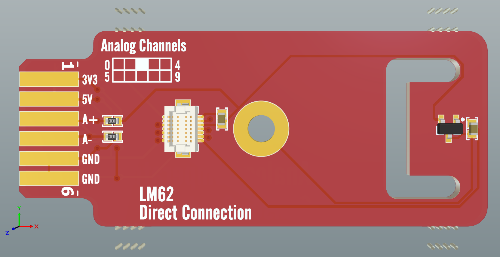
The board is laid out very similarly to the LM87, with the power supply decoupling capacitor next to the sensor IC, and the sensor’s output voltage decoupled near the stacking connectors.
Analog Sensor Implementation: Maxim Integrated MAX6605MXK
The MAX6605 by Maxim Integrated is another modern temperature sensor in the same small SC70 package as the LMT87. At 25°C, the MAX6605 has a temperature error of +/- 0.75°C. However, over its full range, that error increases to a maximum of +/- 5.8°C, which might not sound fantastic, though this is for a sensing range of -55°C to 125°C. In the 0°C to 70°C range, where most household devices would commonly operate, its temperature error is +/- 3.0°C.
Driving a typical ADC, the temperature sensor would consume around 10 uA of current, which relates to an increase of the die temperature above ambient of just 0.0162°C, far better than the LM62 we looked at above. This low power consumption also makes the MAX6605 capable of being powered directly by a microcontroller or other logic device pin, which can facilitate its autonomous switching on and off to optimize the power consumption.
Reading the datasheet, I thought it was interesting that it states that there are 572 transistors in the device. Texas Instruments don’t have this level of information in their temperature sensor datasheets. Still, it goes to show how much more is going on inside an integrated circuit temperature sensor compared with the circuits we’ve looked at previously with a resistive element and an operational amplifier. For comparison, the LM741 operational amplifier contains just 20 transistors. This shows that while temperature sensors may seem to be rather simple, they are actually quite complicated devices.
The MAX6605 recommends an input decoupling capacitor of 0.1 uF, whereas the other sensors we have looked at can both operate satisfactorily without an input capacitor.
As there is no suggestion in the datasheet for adding an output capacitor, so I won’t add one for the MAX6605.
.png)
The PCB for the MAX6605 is nice and straightforward, with just the decoupling capacitor and sensor IC to add.
Conclusion
Analog temperature sensor ICs are an easy way to add a relatively precise sensor to your circuit board, whether you’re looking to sense ambient temperature or the temperature of a specific component or area of your board. With many options not requiring any external circuitry, they offer a highly compact and cost-effective solution.
In this article, we’ve only looked at three sensors out of the hundreds of devices that are regularly stocked by the major suppliers. You should take a look at analog temperature sensors available on Octopart to get an idea of the range of capabilities offered. There’s an option suitable for every budget and application you can think of, whether you want a voltage output similar to what we’ve looked at here, or a current source that varies with temperature.
In my mind, with the vast array of communication interfaces available on modern microcontrollers and other logic devices, an analog temperature sensor would typically only be useful with other analog circuitry, or if your budget was of primary concern. Analog temperature sensors are perfect for creating thermostats for powering up a fan when a circuit board gets too hot, or for turning on a heater when a board gets too cold. Building this functionality with circuitry rather than firmware can reduce development time for non-configurable options, save clock cycles, and also increase reliability. By not having to rely on code to do what needs to be done when it needs to be done, we can ensure that the board’s thermal management will continue to run smoothly no matter what the logic device is doing. We don’t have to worry if, for example, the code has locked up or is too busy to deal with an interrupt caused by a thermal issue in a timely manner.
In the next article, we’ll be looking at digital temperature sensors. These are perfect for integrating high precision temperature readings into a microcontroller’s processing. Whether you need to report/log a temperature, display it to a user, or perform some other actions based on absolute or changes in temperature. Having a digital temperature sensor can allow you to skip ADC calibrations and get the exact sensed temperature transferred directly into memory.
Would you like to find out more about how Altium can help you with your next PCB design? Talk to an expert at Altium.