Continuous Conduction Mode in an SMPS: What is it and Why it Matters
Switched-mode power supplies seem simple enough to design and analyze: it seems like you plug in wall power, and you get out a stable DC voltage, right? I think it would be great if power supply design was that simple, but that is not really the case. Things like topology, component selection, layout decisions, isolation, and grounding all influence noise, stability, and transients in the supply’s output response. One factor that isn’t always considered in switching power supplies is the conduction mode, or how the energy storage section and components release energy to deliver power to the output terminals.
The continuous conduction mode is often desired by default when designing power supplies, but there is also a discontinuous conduction mode that can be accessed in switching power supplies. To summarize what this means, the energy stored in a coil in a power supply will drop to zero in the discontinuous conduction mode, and it never drops to zero in the continuous conduction mode. As far as power delivery and what you would measure, the current in the coil will cross 0 A due to switching in the discontinuous mode, while it will not cross 0 A in the continuous mode.
Why is this important, and which mode should we try to reach in a power supply? We’d prefer the continuous mode, but it’s important to understand why we might end up in the discontinuous mode and what tradeoffs are involved. Let’s look at some reasons to reach for the continuous conduction mode in your regulator design and how you can tell if you’ve reached the discontinuous mode.
Why the Continuous Conduction Mode is Important
As was mentioned above, the continuous conduction mode in a power supply is reached when the current in the charging/discharging coil never drops to or crosses over 0 A. If you look at the waveform for the inductor current in a switching converter, you can quite easily see whether the system is operating in the continuous or discontinuous mode. As long as the current in the inductor is always pointing in the same direction as the input current, then you’re operating in the continuous conduction mode.
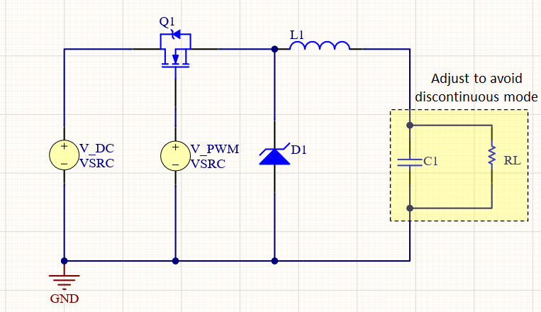
The graph below shows an example of what can happen in the discontinuous mode. Here, I’ve simulated a simple buck topology with 50% duty cycle @100 kHz and a small inductor (only 500 nH) connected to a very small (10 Ohm) load. Here, we see that the inductor current briefly drops to -40 mA while the switch is on due to undershoot in the transient waveform. When the switch is off, we see that the OFF-state circuit is an underdamped RLC oscillator, where the inductor current oscillates around 0 A before the next PWM cycle. Note the peak in the transient response reaches approximately -200 mA during this oscillation with significant ringing, making this a rather undesired inductor current.
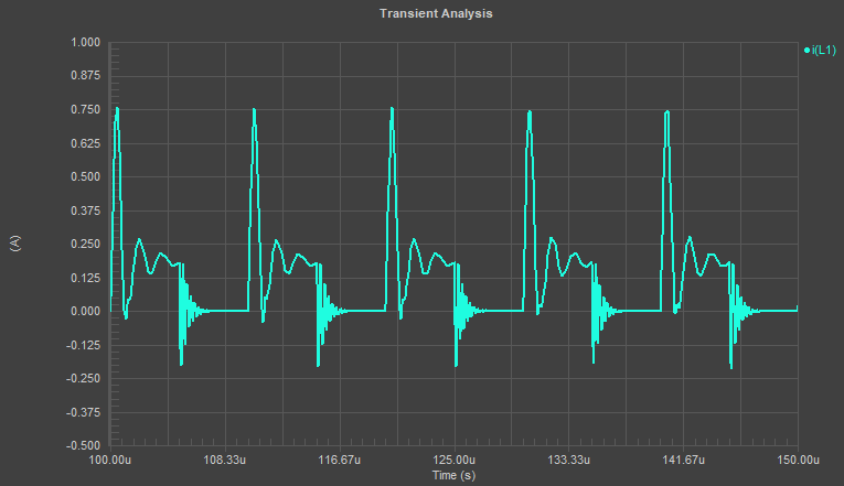
In light of the above graph, it’s a fair question to ask: why do we care about the continuous conduction mode? There are several reasons:
- In discontinuous conduction mode, the output voltage depends on the duty cycle, inductor size, PWM frequency, and the input voltage value. In continuous conduction mode, the output voltage only depends on the PWM duty cycle.
- This means that simply adjusting the duty cycle to compensate for changes in the input voltage is no longer a useful control strategy when in the discontinuous mode.
- As we see above, in the discontinuous conduction mode, there is a potentially undesired transient response in the inductor current that can propagate to the output voltage.
- The transient response in the inductor current can be underdamped with some ringing during PWM switching, leading to EMI emission at high currents.
In point 1 above, I’ve ignored any of the nonlinear effects in the switching MOSFET, but these points are valid regardless. If you’re designing a power converter to operate at one specific PWM frequency and duty cycle, and there is no feedback sensing or PWM adjustment, then you’re probably not worried about the continuous conduction mode. As long as you get the power you want and EMI isn’t too terrible, then don’t worry about it. Real systems that require precise control over the regulator output and low EMI should opt for continuous conduction mode designs as there is only one lever needed to compensate for changes in the output voltage.
Designing for the Continuous Conduction Mode
If the load in the system is too low, your SMPS will enter the discontinuous conduction mode. The process for designing to the continuous conduction mode follows a specific process: select the desired output voltage, calculate the coil inductance and output capacitor values, and select the PWM driver parameters. These tasks can be performed for a target load resistance value.
What Happens in Discontinuous Mode
When you’re operating in the discontinuous conduction mode, the output voltage will depend on the inductor value, PWM frequency, and duty cycle. For simple topologies with a single PWM source and MOSFET, the output voltage is given by the following equations:
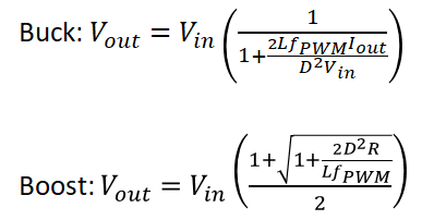
The above equations are well-known. I don’t often reference Wikipedia, but their articles on buck and boost converters contain the derivations of these equations. Follow their steps if you want to derive expressions for more complex converter topologies and determine the output voltage, inductor current, and the border between discontinuous and continuous conduction.
Pick the Right Inductor for Continuous Conduction Mode
There are a couple other points to notice both from the above equations and from the basic function of an inductor in a DC-DC converter:
- The inductor should generally be large to dampen the ripple current. As it turns out, there is also a minimum inductor value that will ensure continuous conduction mode operation. From the above, we see that the correct in discontinuous mode vanishes as L → infinity.
- The output capacitor should also be large, both to suppress ripple and to ensure slow discharge when the inductor is releasing energy. There is a minimum output capacitance value for a given ripple current and load that will ensure the design operations in the continuous conduction mode.
While the equations for minimum capacitance and inductance are found in many application notes for basic buck/boost designs, more complex topologies can be difficult to analyze, and SPICE simulations can be used to determine the minimum load resistance that will ensure your converter operates in the continuous conduction mode.
What to Evaluate in Your Design
Obviously, the inductor current should be evaluated in a SPICE simulation when checking for continuous conduction mode operation. The design strategy for ensuring the inductor current does not fall to zero during switching is to iterate through values for other circuit elements, namely the output capacitance and load resistance values. Run through different load and capacitor values to find a region where the inductor current remains positive for your chosen PWM parameters.
Nonlinear effects in the MOSFET will also influence the rise/fall time of the inductor current, so the PWM driving voltage and the range of input values might also be design candidates for avoiding discontinuous operation. Make sure you have a valid simulation model for your MOSFETs and make use of DC sweeps to spot the linear range for your converter when selecting PWM parameters.
No matter what switching regulator topology you want to use in your design, make sure to use the best set of CAD tools and circuit simulation features in Altium Designer®. When you’ve finished your design, and you want to release files to your manufacturer, the Altium 365™ platform makes it easy to collaborate and share your projects. We have only scratched the surface of what is possible to do with Altium Designer on Altium 365. You can check the product page for a more in-depth feature description or one of the On-Demand Webinars.
