What Target Impedance Should You Use in Your PDN?

A number of us on this blog and in other publications often bring up the concept of target impedance when discussing power integrity in high speed designs. Some designs will be simple enough (and slow enough) that you can take a “set it and forget it” approach to designing a functional prototype; as long as you follow a few general guidelines, power integrity is generally assured and the design can be fine-tuned to bring it to production level. For more advanced designs, or if you’re fine-tuning a new board that has existing power integrity problems, target impedance is a real consideration that should be considered in your design.
One question I’ve been asked is simple, and yet it’s overlooked by so many of us who write about power integrity: what should the target impedance be for a particular design or component? It’s a fair question, and some SI/PI guidelines will just tell you to set a target impedance anywhere from 1 to 100 mOhm. The better option is to calculate a target impedance to ensure you don’t over-design or under-design the PDN. Once you calculate the target impedance, you also need to calculate the deviation in the measured (or simulated) impedance from your measured impedance. We’ll look at both points in this article.
How to Calculate Target Impedance
There is no single value of target impedance you should use in your PDN. Although there are several factors to consider when determining an appropriate target impedance, and not all of these will take precedence in your design. The goal of setting a target PDN impedance is to ensure that switching events in your digital ICs or high-frequency analog circuits do not produce excessively large transient oscillations on your PDN (supply and ground bounce).
Remember from discussions of ground bounce and supply bounce that switching signals in an IC will draw pulses of current into the PDN, which can excite a transient oscillation in the power bus voltage seen at the IC in question (supply bounce) and create high-frequency transient oscillations seen on the outputs from the IC (ground bounce). If you look at the article linked above, you’ll see an excellent example of a measurement showing both effects in the same oscilloscope trace.
Since we know current draw into the PDN creates some voltage fluctuation on the output port of the PDN, we can relate the current being drawn into the PDN to the impedance of the PDN and the voltage disturbance seen on the main power bus via Ohm’s law:

In essence, if you measure your voltage on the power bus with respect to the PDN’s reference plane, you would measure the nominal DC voltage plus ΔV. I’ve used the Δ notation to indicate these are fluctuations, or rather values that are changing in time. Since the power bus draws in some ΔI during switching, and we want to minimize ΔV, we need to also minimize ZPDN.
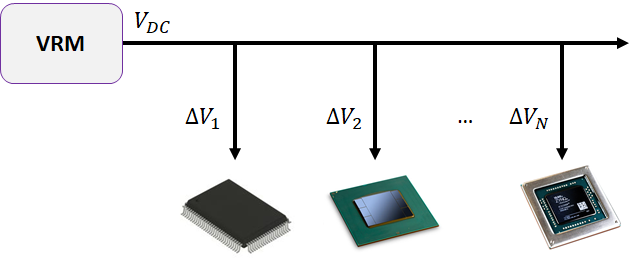
This is more complicated than just looking at a single large IC. Some digital designs can have multiple large ICs connected to multiple voltage levels, with the bus for each level shared with other components that might also draw current in fast pulses. Therefore, we need to think about the structure of the PDN to get a reasonable estimate for the target impedance. The best option is to think of the system as a multi-port PDN.
About Multi-port PDNs?
A multi-port PDN typically has 1 input and N outputs connected to a main power bus, so you have a Z-parameter matrix instead of a single PDN impedance value. Flipping this around, you can even have a single IC (see the BGA component below) that has multiple power levels, each requiring its own bus and regulator. In this way, you technically have multiple subsections in your PDN with each requiring extensive decoupling.

The above equation for Ohm’s law would now be written as a matrix equation relating the voltage measured at each output port to the current drawn into each port. You would then have to invert this equation to solve for the impedance matrix [Z] for a given tolerable ripple and current.

Obviously, we could spend an entire article (or more) going into this whole conversion. However, if you realize that the ripple created at 1 port in the PDN superimposes itself onto all other ports in the PDN via Kirchhoff’s voltage law, you can find a minimum ripple value and target impedance with the following process:
- Calculate the allowed ripple seen at each port
- Use the total expected current draw into the PDN
- Use the smallest ripple value from Step 1 and the total current from Step 2 to calculate the target impedance
The idea here is simple; just use the lower limit of the target impedance as your design goal in the entire PDN, rather than trying to design every entry in the Z-parameter matrix to have a specific value.
Calculating ΔV and Z
We’re now back to the crux of this conversation: what’s the best way to calculate the allowed value of ΔV? For a given port on your PDN model, you have a few options to set a target impedance:
- Look at the core voltage level on your IC, and calculate an allowed fluctuation within the core’s allowed noise margin using some safety factor.
- For high-precision applications, consider looking at the jitter imposed on the output. This is more difficult to determine without measurements and can be on the order of 1 ps/mV. High precision applications could require much less than 100 ps jitter to ensure accuracy (e.g., lidar ranging and imaging).
- Calculate the voltage fluctuation on any output due to current drawn into a buffer circuit during switching. For this, you’ll need the pin inductance value from the component datasheet and the inductance of any via going back to GND.
Next, assuming you know the current levels in the high and low states, you can now determine the target impedance from Ohm’s law using your determined ripple and maximum current draw into the PDN:

This is a rather conservative value for target impedance you can aim for in your design. This is because you’re using the maximum transient current, whereas most other guidelines will state to take an arbitrary 50% of this value. This whole process also avoids being unnecessarily accurate. Normally, if you wanted to calculate the target impedance from Ohm’s law, you would need to use a convolution (in the time-domain) to get the impedance impulse response, followed by a Fourier transform to get the target impedance spectrum. Instead, the above process doesn’t need any integrals!
Once you’ve determined the target impedance you need to use in your PDN, you can define the right layer stack, PCB layout, cap placement, and much more with the best PCB layout tools in Altium Designer®. When you need to evaluate power integrity and EMI in your PCB layout, Altium Designer users can use the EDB Exporter extension to import designs into Ansys field solvers and perform a range of SI/PI simulations. When you’ve finished your design, and you want to release files to your manufacturer, the Altium 365™ platform makes it easy to collaborate and share your projects.
We have only scratched the surface of what’s possible with Altium Designer on Altium 365. Start your free trial of Altium Designer + Altium 365 today.
