Types of PCB Soldering and the Assembly Process
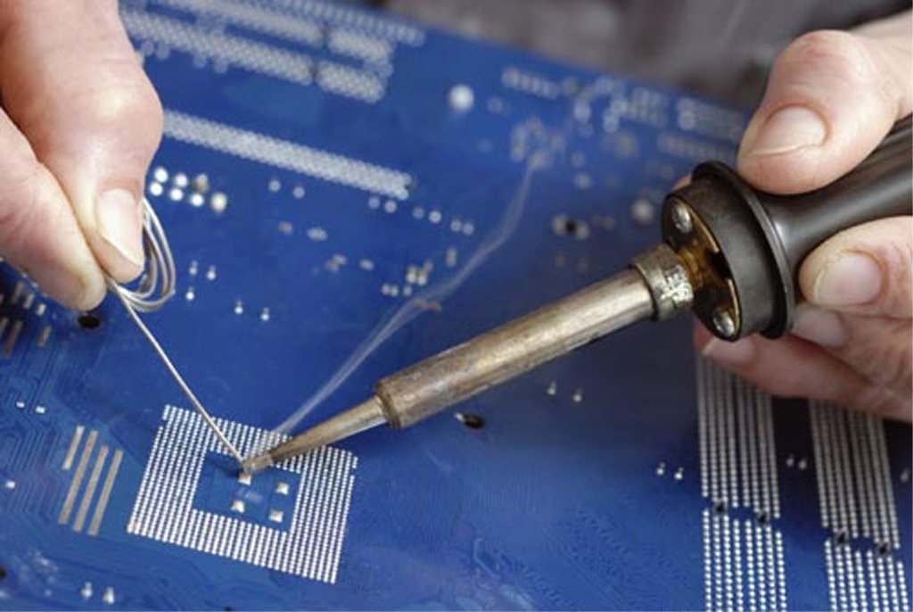
I remember when I first started working in a lab and had to occasionally solder wire leads onto metalized contacts. We were working with semiconductor materials, but the same materials can be used in PCB soldering, it’s all a matter of choosing the right blend to fit into the PCB manufacturing process.
The PCB manufacturing process involves multiple steps, spanning from bare board fabrication to assembly and packaging. As part of PCB assembly, there are different types of PCB solder used to mount components. Different solders have different mechanical characteristics, safety considerations, and disposal concerns that should be considered when planning for assembly. The transition to lead-free electronics is pushing the use of lead-based solder to the margins.
I won’t get into the lead-based vs. lead-free debate just yet as the internet has plenty to say about this. For now, let’s stick to looking at the different types of PCB soldering, specifically different materials and processes.
PCB Soldering Materials
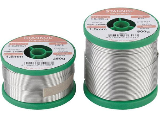
There are many different kinds of solder available on the market, and picking the best type of solder might seem like a daunting task for the new designer or assembler. Solders are used to make electrical connections between metal contacts by allowing molten solder (which is a soft alloy) to form a eutectic that fuses as it cools. The blend of metals that makes up a solder will determine its mechanical strength after solidification, the required melting temperature, and any fumes put off during soldering. We can distinguish types of PCB soldering materials by core material, metallic constituents, and types of soldering flux.
Metallic Content
Lead solder blends are known as soft solders and are responsible for kicking off the electronics industry. They have a melting point of around 180-190 °C and shelf life of about 2 years. Common lead-based solder alloys include:
- 60/40 Sn/Pb
- 63/37 Sn/Pb
- 62/36/2 Sn/Pb/Ag
Other Sn/Pb ratios include 50/50, 30/70, and 10/90. Tin is primarily used as the base metal as it gives the alloy a lower melting point, and the lead inhibits the growth of tin whiskers. A higher tin concentration ensures the solder joint has higher shear and tensile strength. The silver component in 62/36/2 Sn/Pb/Ag provides lower contact resistance and corrosion resistance. Note that there are other types of solder (indium, zinc alloy, etc.), but these are not used on PCBs as they are incompatible with the PCB manufacturing process.
Lead-free solders are gaining more popularity ever since the EU passed the Restriction of Hazardous Substances (RoHS) Directive, which restricts the use of lead in electronics. One problem with lead-free solders is that they are more likely to form tin whiskers. Conformal coatings are often used to prevent these tin whiskers from forming and to provide protection from humidity and corrosion.
Flux core solder is sold as a single reel and contains a reducing agent in the core. This reducing agent (I’ll discuss below) removes any oxide film on the metal contacts to ensure an electrical contact with high conductivity. The type of material contained in the core is another point to consider if you are soldering by hand.
Solder Core Material
Spools of solder or solder pastes will contain one of these types of materials to flux the metal contacts during soldering:
- Organic acid flux: An acid-based flux ensures aggressive removal of oxides from metal contacts as they are soldered. This flux is water soluble and requires residues be cleaned after soldering to prevent corrosion.
- Rosin flux: Rosin is a solid form of resin derived from conifers. Rosin flux residue will not cause corrosion, so it is used whenever it may be more difficult to remove residue from organic acid flux.
- Solid core solders: Some solder wire has a solid core and does not contain any flux, so flux needs to be applied by hand. This type of solder is useful for hand soldering as long as flux is available.
PCB Soldering Processes
Today, the most common type of solder is lead-free (Sn-Cu) rosin core solder. Unless your assembler is working a one-off board or you are assembling your own board, the PCBA will not be soldered by hand. Instead, it will go through an automated process:
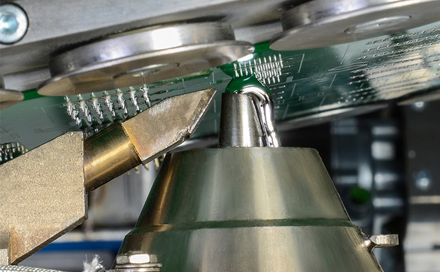
- Wave soldering: Used for through-hole components
- Reflow soldering: Used for SMT components in a reflow oven
- Selective soldering: Used when a through-hole component might be damaged by high heat or is unsuitable for the wave and reflow processes
Flux/paste is first applied to the metal contacts on the board to reduce oxidation and even out the flow of molten solder, which strengthens the finished solder joint. Most designers will probably assume that you need to assemble parts with Pb-free leads using a Pb-free solder paste, but this is not a strict requirement. According to a panel of soldering experts, it’s not uncommon to mix these materials, although be aware that the final alloy you form may have mechanical properties that lie in-between the final Pb-based and Pb-free alloys.
When you need to generate manufacturing deliverables for your board, including any required assembly steps and conformance to regulations, use the complete set of PCB design and production features in Altium Designer®. Once you generate your Gerber files and other fabrication files, you can quickly create assembly drawings and add annotations to specify your assembly requirements. It’s easy to specify the different types of PCB soldering materials you might want to use in your next PCBA.
When you’ve finished your design, and you want to release files to your manufacturer, the Altium 365™ platform makes it easy to collaborate and share your projects. We have only scratched the surface of what is possible to do with Altium Designer on Altium 365. You can check the product page for a more in-depth feature description or one of the On-Demand Webinars.
