Standards for PCB Thermal Shock Testing
Electronic components generate heat while they operate, which will heat up the rest of your board. Heat will move to cooler areas of the board, but a board that reaches high temperature without quickly dissipating heat is prone to failure. Thermal shock testing aims to evaluate a design to ensure it can withstand thermal shock and comply with important application requirements. The best set of design tools, like the circuit board layout features Altium Designer, can help designers identify and correct any design defects that can lead to failure under thermal shock.
ALTIUM DESIGNER
A unified PCB design package that integrates advanced PCB layout tools with assembly and manufacturing preparation features.
Designers should always do their best to ensure their boards are kept cool during operation. Although designers often include features like thermal vias, heat sinks and fans, extra copper, and bonding with thermal interface materials, these don’t provide complete protection against thermal shock. When thermal shock occurs, it can cause a circuit board or its components to fail, and boards for many rugged applications need to be tested for thermal shock reliability.
Thermal shock testing follows multiple standards, and thermally reliable products should be designed to withstand the demands of these thermal tests. With the best set of design tools, a design team can implement the thermal management approach that helps prevent failure due to thermal shock. If your next design will be deployed in a rugged environment, then you should plan for thermal shock testing and design your board to withstand these tests.
Understanding Thermal Reliability in a Circuit Board.
Thermal shock testing involves bringing a board to a high temperature in a short amount of time and held at that temperature. After the test, the board is brought online to inspect for damage or failure. What qualifies as a board failure is product-specific, but the industry standards that govern thermal shock testing are universal. Designing for thermal reliability requires understanding examining structural reliability and failure in the circuit board, as well as component reliability and failure:
- Thermal shock reliability. When a board is exposed to very high temperature, it can heat up very quickly, which may cause mechanical components or conductors on the board to fail under thermo-mechanical stress.
- Thermal cycling. Thermal shocks can happen repeatedly. Even though the board may not heat up to high enough temperature to fail instantly, damage can accumulate over time as the PBC temperature is repeatedly cycled between two extreme values. Over time, conductors can become fatigued (e.g., through micro-cracking, corrosion, or pitting) and elastic materials can become embrittled.
- Component failure. Components can fail immediately via multiple mechanisms. This can occur even if the board withstands a thermal shock. Some failure mechanisms are component-specific and the required thermal shock testing must be determined on a per-product basis.
There are specific standards that designers must consider when designing a board to ensure thermal shock reliability.
IPC-TM-650 2.6.7 Thermal Shock Testing
The IPC-TM-650 2.6.7 standards are general thermal shock testing requirements based on MIL-STD standards. These standards are applicable to multiple materials used in circuit boards. The IPC-TM-650 2.6.7 standard specifies the test temperature range as a multiple of the PCB substrate’s glass transition temperature (Tg) for the board’s substrate or over a standard range (MIL-STD-202G). In this test, IPC-D test coupons are specified to be subjected to thermal shocks ranging from -55 °C to the minimum of: Tg - 10 °C, reflow temperature – 25 °C, or 210 °C, which covers typical temperatures for a wide range of materials.
MIL-STD-202G Thermal Shock Testing
MIL-STD-202G, Method 107 is another standard thermal shock testing methodology for defense military equipment. This standard applies to air-to-air methods or liquid-to-liquid methods, where a board is simply transferred between hot and cool air, or between hot and cool liquids. This determines the rate of heat transfer during the test.
These test standards cover a broad range of conditions that might be seen in consumer, industrial, aerospace, and military applications. Before designing your PCB layout with the best design software, take some time to understand what circuit board layout features determine thermal reliability.
- Microvias are prone to fracture along the neck and base due to thermal shock, including during reflow and wave soldering.
Learn more about microvia reliability and fracture due to thermal stress and shock.
- Burn-in testing is used to ensure components and circuit boards that might fail early are identified and removed from component lots.
Learn more about burn-in tested components for your circuit board.
- Fabricators and assemblers can be a great resource for helping you design your board to withstand thermal shock tests.

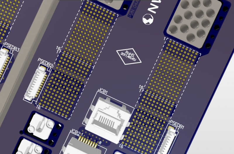
Backplane design in Altium Designer.
Designing Circuit Boards for Thermal Reliability
There are many decisions a designer can make to ensure a board has high reliability. It all starts with selecting the right PCB substrate material that can withstand high heat without large thermal expansion. The materials in your circuit board and components will determine how heat is transferred around the board during operation, and how the board expands when it experiences thermal shock.
Other important aspects of a PCB layout include use of copper and arrangement of components to help prevent hotspots from forming during operation. There are some simple design choices that will influence the final temperature of your board if it experiences thermal shock:
- Use PCB substrate materials with high thermal conductivity
- Use thermal vias and grounded polygon pour to remove heat from components
- Use heatsinks and fans on critical components
- Use a PCB substrate material with a high Tg value
- Use additional copper pour and plane layers to control heat dissipation
- Use a thermal interface material to bond the board to its enclosure
Once your prototype is created, it should be put through thermal shock testing to ensure these design decisions are valid. The best PCB design software like Altium Designer will include the features you need to implement any of the design choices listed above.
Using the Best PCB Design Software for Reliable Circuit Boards
Altium Designer includes CAD tools, layout utilities, and routing features to help designers apply any of the above thermal reliability measures and much more. In particular, the stackup manager in Altium Designer lets designers select from a library of common core/prepreg materials, or a designer can enter materials data for a custom material. This gives designers full control over their PCB stackup design when building products for use in rugged environments.
- PCB substrate materials with high thermal conductivity, like metal-core circuit boards or ceramics, can help control heat flow and help keep your components running at low temperature.
- Passive cooling with a heatsink is aided when a designer uses a thermal pad or thermal paste to bond a heatsink to hot components.
Learn more about thermal paste and thermal pads on heatsinks.
- Vias should be properly designed with annular rings and aspect ratio that is not too large. These simple choices can help prevent component and interconnect failure.
Learn more about designing reliable vias in your PCB layout.

Design your board with the best set of design tools to ensure reliability.
Prepare Your Board for Manufacturing and Testing in Altium Designer
Fabrication and assembly are where your design will be put to the test, and a manufactured design will need to be thoroughly tested for reliability. Electrical testing, thermal testing, mechanical testing, and functional testing need to be performed, and the best PCB design software can help you prepare your design for full-scale fabrication and testing.
Altium Designer includes automated design documentation tools that help you prepare for production without using an external program. Altium Designer speeds up the production process by preparing documentation directly from your design data. It’s simple to prepare a design for fabrication and assembly thanks to the complete set of PCB layout tools in Altium Designer. Once you’re ready to send your board off for manufacturing, it’s easy to send a design out for manufacturing through the Altium 365 platform.
Altium Designer is the Best Software for Building Reliable Circuit Boards
The rules-driven design environment in Altium Designer is key to designing a circuit board for reliability. The online DRC engine catches layout errors whenever they are created, including layout problems that can cause a board to fail thermal shock testing. You can keep your design team operating at peak efficiency with Altium Designer.
- Altium Designer’s rules-driven design engine creates a productive experience and helps ensure circuit board layouts are error-free.
Learn more about Altium Designer’s unified design environment.
- Only Altium Designer contains a complete set of professional PCB design features that anyone can use to build high-quality electronics.
Learn more about the comprehensive PCB design tools in Altium Designer.
- When you need to share your circuit board projects with other PCB designers or your manufacturer, Altium 365 lets you instantly share your design and production data on the web or through Altium Designer.
Learn more about sharing your PCB project data with Altium 365.

Altium Designer includes a comprehensive set of PCB design and layout utilities for any electronic product.
If you need to prepare a new design for manufacturing and thermal shock testing, don’t use a set of 3rd party design and manufacturing programs. Use Altium Designer to implement best practices for thermal reliability and to prepare your new design for production. No other design application provides a complete set of design, sharing, and design verification features in a single application.
Altium Designer on Altium 365 delivers unprecedented integration to the electronics industry until now relegated to the world of software development, allowing designers to work from home and reach unprecedented levels of efficiency.
We have only scratched the surface of what is possible to do with Altium Designer on Altium 365. You can check theproduct page for a more in-depth feature description or one of theOn-Demand Webinars.
