S-Parameter Measurements and Errors in Power Integrity

No matter where you look, it seems S-parameters never go away! They are mandatory tools for understanding some systems, such as an interconnect or antenna, while other network parameters can sometimes give a better conceptual understanding of electrical behavior. These parameters are normally reserved for signal integrity among electronics engineers, but if you look hard enough, you’ll find that S-parameters are also used for power integrity. This should make sense intuitively simply from a power flow perspective: Kurokawa’s original formulation of S-parameters was in terms of power carried by a signal, so why not use this for power integrity?
In PDN design, particularly for high speed digital components, we care about designing to a low PDN impedance. Low PDN impedance leads to low voltage disturbances measured between power rails for a given transient current draw. Network parameters can be used to characterize the PDN and determine its impedance, but the use of S-parameters requires the use of the appropriate reference (port) impedance for an accurate PDN impedance calculation. Let’s look at exactly how errors in S-parameter measurements propagate into Z-parameter measurements in a simple case to gain some intuition, then I’ll discuss general N-port PDNs and how errors in the S-parameter matrix create errors in the impedance matrix.
S-Parameters and Power Integrity
When measuring S-parameters, every measurement will be bandlimited and discretely sampled. This leads to errors in the measurement that are unavoidable. In other words, the S-parameters you measure are not the true S-parameters, leading to problems with causality. Since S-parameters can be used to calculate other network parameters (including Z-parameters), how does the S-parameter error influence the Z-parameter error? Let’s look at this for a 2-port PDN, then an N-port PDN.
Errors in 2-Port PDNs with Large S11
First, let’s look at errors in a 2-port PDN as this is an easy problem we can solve to get some insight. To get started, we can use a basic conversion to relate the S-parameters in our PDN back to the Z-parameters, then calculate the Z-parameters in the presence of some error.
In the following equation, I’ve defined my PDN self-impedance in terms of an S-parameter matrix for the PDN in the presence of 2 errors. The e term is my S11/S22 error, and the f term is my S21/S12 error. Assuming reciprocity holds (Sij = Sji), we have:

Just to focus on the critical aspects of self-impedance, let's assume the PDN is reciprocal and lossless. In this case, the S-parameters are S21 = S12 = 0 and S11 = S22, and the above equation reduces to the familiar conversion between S11 and self-impedance. We can get a good approximation on the Z11 error if we take the difference between the high and low error as defined above, and by setting and squared error terms to zero (i.e., e2 << e). This gives the following simple expression for errors in the PDN impedance due to measurement errors in S11:

In this example, let’s suppose that S11 = -0.9 in our hypothetical lossless reciprocal PDN. In this case, a 1% error in my S-parameter measurement translates into a 10.5% error in Z11. That’s a 10-fold amplification in error!
That may seem like a major mistake, but it matches with remarks from other experts in this area. In particular, note the remark on page 8 of this study from Keysight, where a 1-2% error in S-parameter measurements leads to a PDN impedance measurement of 300 to 400 mOhms. Just for a sanity check, let’s bring this back into our example. When the true impedance is ~10 mOhms and the standard VNA port impedance of 50 Ohms is used, we have S11 = -0.9996 and Z11 measurement error of 250%. Such large impedance mismatches at the input port are highly undesirable when we’re trying to use S-parameters to determine PDN impedance.
Errors in 2-Port PDNs with Small S11
Now let’s suppose my reference impedance is brought much closer to my PDN impedance so that S11= 0.1 with up to 1% error. The error in the Z11 is now only 2.02%. When we have very close matching to the true PDN impedance, we have a reduction in error in the calculated Z11 value. As it turns out, the critical S11 value in this example where your PDN impedance error will perfectly match your S-parameter measurement error is S11 = 0.268.
This should show how a large impedance mismatch amplifies S-parameter error measurements when calculating the impedance parameters for a 2-port PDN. Note that this is frequency dependent, but the process applies at each frequency measurement; you might have very accurate impedance at some frequencies, and your results might be very inaccurate at others. This can then be extended to N-port networks using the general S-to-Z-parameter conversion.
Errors in N-Port PDNs
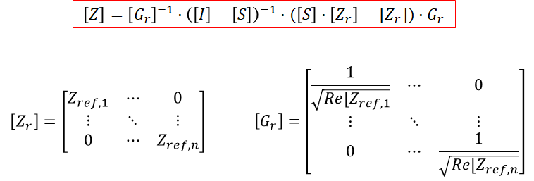
N-port problems are much more difficult to deal with analytically; this requires using the general Z-parameter matrix for an N-port network (including self-impedances and transfer impedances). In general, you’ll need to perform the same process as detailed above, but with a general S-to-Z-parameter conversion matrix for an N-port network:

This takes a ton of algebra just to derive an expression relating S-parameter errors to Z-parameter errors. Therefore, this problem of solving such a matrix for a set of S-parameter measurements and port impedances is best solved with Matlab or Mathematica. The point here is, the error is going to be inversely proportional to products of squared (1 - S) terms. Therefore, we’re going to have a situation where an N output port PDN will need to have its reference impedance approximately reduced by a factor N to ensure the error will be low.
What Reference Impedance Should be Used?
From the above discussion, it seems you would want as small of an impedance mismatch as possible if you were using a VNA to measure the S-parameters for an N-port PDN, and then use these measurements to determine the impedance matrix. This would then give you the smallest possible error magnitude in your Z-parameters for a given S-parameter measurement error. Since the PDN impedance is at mOhm levels, your reference impedance should also be around mOhm levels, not at the 50 Ohm level normally set in commercial VNAs.
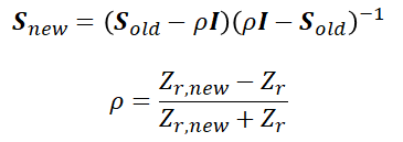
Finally, if you apply renormalization to drop down the S-parameter reference to be closer to the PDN impedance (maybe down to 50 mOhms), the error term also propagates nonlinearly because normalization involves an S-parameter multiplication operation. In other words, there may be some S-parameter values squared, which may amplify the error in the Z-parameter values you calculate. I’ll leave this up to the reader, just apply the following equation and calculate the Z-parameter values with the processes I’ve described above.

When you need to design your PDN to ensure ultra-stable power delivery and manufacturability, use the complete set of layout and routing features in Altium Designer®. The board stackup and layout tools in Altium Designer are the best for creating high-quality boards while also staying productive.
When you’ve finished your design, and you want to share your project, the Altium 365™ platform makes it easy to collaborate with other designers. We have only scratched the surface of what is possible to do with Altium Designer on Altium 365. You can check the product page for a more in-depth feature description or one of the On-Demand Webinars.
