Designing for Multiple PCBs in the Same Project

Majority of our PCB designs sit as a single PCB under our Altium Designer projects (i.e. .PrjPcb file). Now and then, we design using variants with different stuffing options. It seldom happens that we have a single project that requires multiple PCBs with various stuffing options, but when it happens, a lot of us tend to get stuck. All too many times, I have seen designers fork (i.e., copy and paste) a project and then add slight variations to the schematic and/or PCB. Generally, this practice would be acceptable except when you need to go back and update the design. How do you handle the exact change across both projects? How do you guarantee those changes to be identical? How many times will this occur (e.g., Rev A, B, C, etc.)? This article will review an approach to managing multiple PCB designs within a single project, ensuring your single source of truth. We will also be reviewing the example using the board from my last article, Pandemic Prototyping: Building Electronics from your Living Room.
Project File Setup
Our objective here is to maintain a single source of truth within the schematics yet be able to route variants of the PCB itself. In this example, I have created a single schematic but with two PCBs:
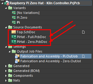
You will also notice the variants at the top. I have created two variants for my Kiln Controller: one for the Raspberry Pi (standard size) and the other for the Raspberry Pi Zero. I started out routing the Raspberry Pi Zero hat design since the standard size is essentially a larger version of the zero. After completing the routing, I copied and pasted the whole PCB design into my standard size PCB (PiHat - Full.PcbDoc). There was some minor massaging required (e.g., cutouts, polygon pours, board outlines, etc.), but the components and routes stayed the same.
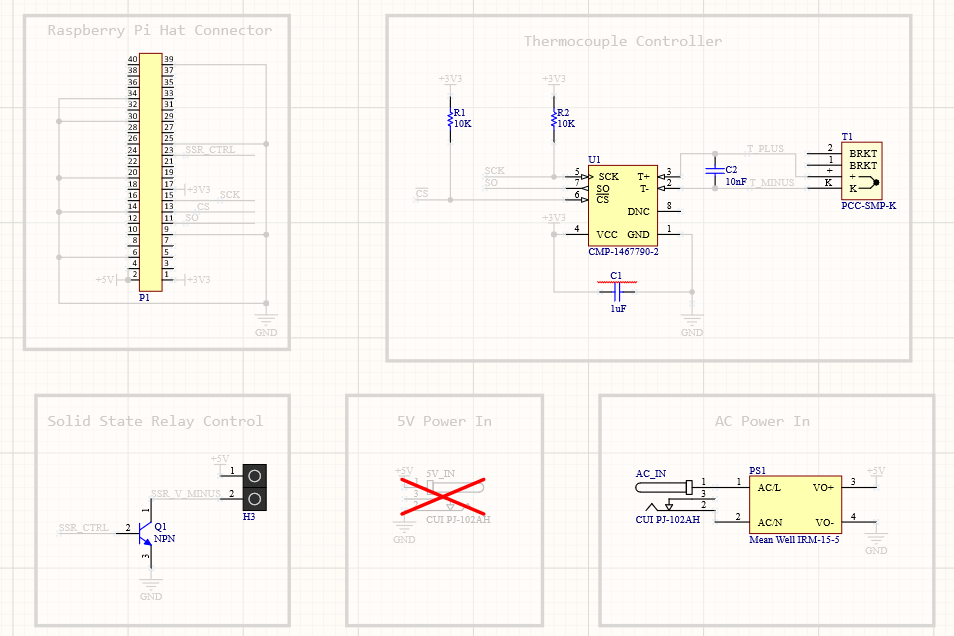
In my schematic, I have included all the components that exist across both designs (whether they are stuffed or not):
_17.png)
I realized that I had a ton of extra room in my standard size Raspberry Pi hat, so I decided to incorporate my AC to DC converter into the board. The problem, of course, is that adding this to the schematic means it will import into my PCB for my smaller Pi hat board. This,full-size is something we do not want to do, so I’ve intentionally excluded it from being brought into my PcbDoc:
_8.png)
Since the components are not in the design, they won’t generate any “unrouted” DRC errors. We also want to add DNI (do not install) options into our variants as well like so:
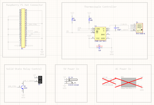
To avoid confusion I completely removed the DC power connector for the full size version (since we’re using an AC input) and vice versa with the Pi Zero version.
Output Job Files
Now that we have designed our schematic, routed our boards, and configured the stuffing options, we need to set up our Output Job files. These Output Job files will generate the fabrication and assembly packages needed to build each board with their respective stuffing options. This is a crucial step that can often get overlooked and cause immense pain down the road when generating a package for the vendor.
In this example, we have a separate Output Job file for each PCB. For simplicity, there is a single Output Job file for both fabrication and assembly (which is generally broken out into two separated .outjob files in the Altium Designer example projects). As you can see in Figures 6 and 7, the .outjob files are identical except for the variant selection and the PcbDoc selection. For multiple stuffing options, we use the variant options located at the top of the window. We generate a package for just the PCB we are interested in for stuffing only the specified PCBs. For example, for the “Pi” variant (which is to stuff a standard size Raspberry Pi hat), we want to select the “PiHat - Full” (i.e., full size) PCB file. We are not interested in generating any fabrication and assembly packages for the Raspberry Pi Zero hat. The same goes for the smaller Raspberry Pi (Zero) hat. We generate the files needed to fabricate and assemble only the board we are interested in.
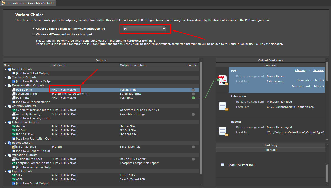
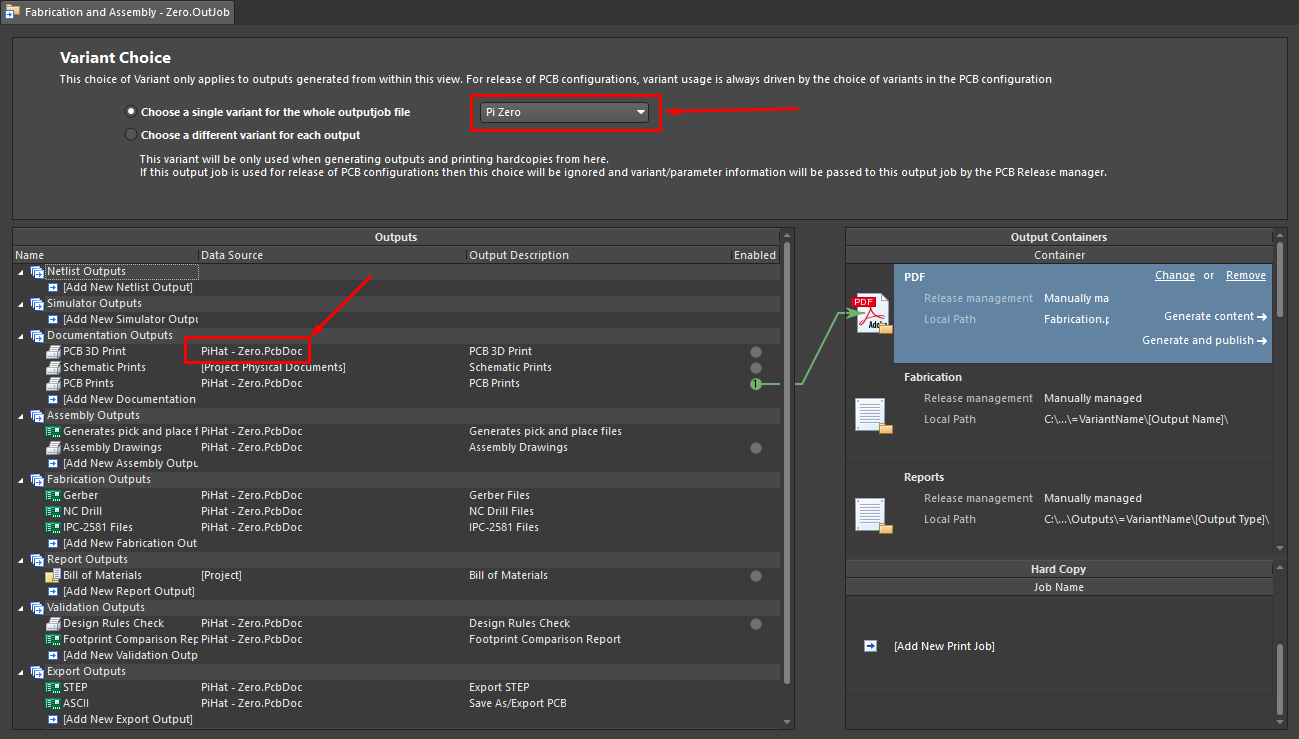
Finally, to enable some reuse, we use the Special Strings in the Folder Structure Settings like so:
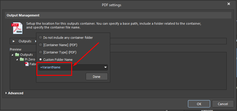
This enables us to have subfolders automatically created based on the variant name. If the variant name changes, so do the folders.
There are more ways to condense these Output Job files even further through scripts or other means, but that is out of the scope of this article. The purpose of this article is to demonstrate how this is possible and provide an example to the reader of one of the many ways to set this up.
Conclusion
This article discussed the challenges designers face with managing multiple PCBs driven from a single source of truth. Rather than create and manage multiple copies of a project, we maintain a single PCB Project while designing for multiple PCBs through Output Job configurations. These configurations enable us to keep multiple PcbDoc files within the project but generate packages for those boards specifically. By utilizing this technique, designers can save time and money by updating a single project that deploys to multiple PCBs.
Would you like to find out more about how Altium can help you with your next PCB design? Talk to an expert at Altium and learn more about making design decisions with ease and confidence.