USB Power Delivery for Your Next Project
Since its introduction in the late 90s, the USB standard has never ceased to grow in popularity. Multiple revisions of the standard have kept it relevant to the growing demands of data delivery, which has made it the ubiquitous choice for electronic devices. There has been a growing trend toward USB being a power delivery interface with data, rather than a data interface that can supply power, as the 1.0 specification originally intended. To supply the increasing thirst for power over USB, the USB 3.0 Spec with Type-C began implementing the USB Power Delivery standard, which you might consider using for your next electronics project.
I’m working on several projects that need far more power than the old USB 2.0 standard (with 2.5W of power) can deliver. I’m charging battery packs or running higher demand loads, which need more voltage. The USB Power Delivery standard was designed to handle situations where you might need to run your laptop or power-intensive tablet device over USB. Doing so requires far more power than 500mA of 5V, and often at higher voltages than 5V USB with power delivery the sink device can negotiate with the source (such as a wall charger) for up to 20V and 5A of current to give a whopping 100W of power to your device. For many applications, this allows you to do away with barrel jacks, specialized power packs, or building AC power into the device, cutting down on waste and reducing your costs.
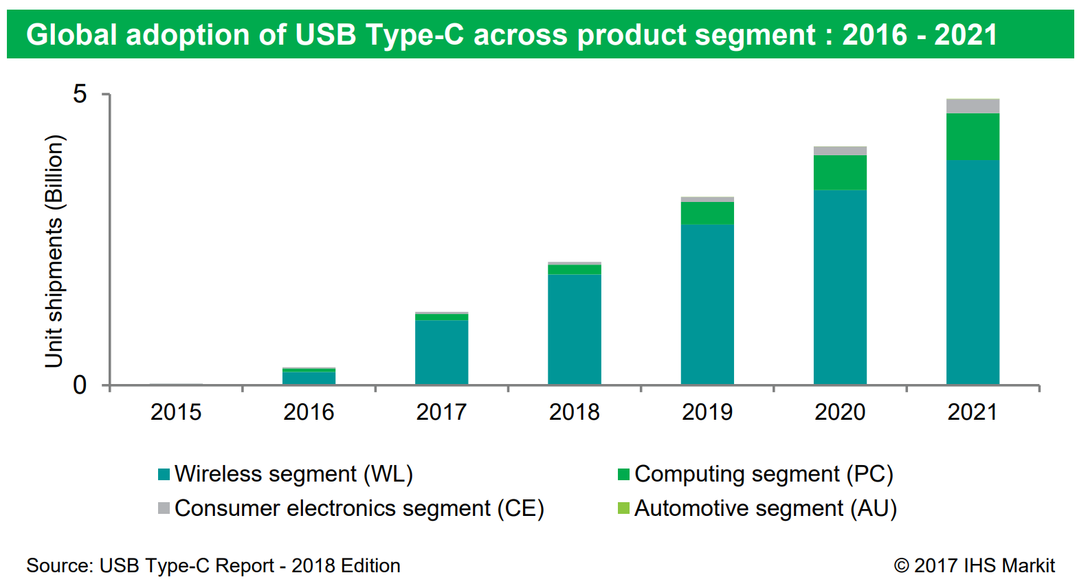
The USB Type-C® connector, released in 2015, has been on the fast-track to becoming one of the most prolific standards on the market, having a projected adoption of 5 Billion units by 2021.
We do not have to look far to understand the technical reasons behind the success. The connector is relatively cheap to manufacture, offers extensive backward compatibility to USB 2 and USB 3 standards, increases the bandwidth available from the USB 2 connector through the addition of 4 extra super-speed data lanes (two more than the two super-speed lanes on the USB 3.0 Type-A connector), offers alternative modes such as HDMI and DisplayPort, is reversible, durable (with often 10x the cycles of micro-USB connectors), and slim.
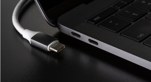
I recently upgraded my phone from one with a USB Micro B connector to USB Type-C, and it’s easy to see why it’s popular from an end-user point of view, not just a technical point of view. Trying to plug the polarized Micro-B into your phone in the dark was somewhat of a challenge, plugging in Type-C is a breeze due to its non-polarized shape. The connector is far more robust as well, which is a big bonus when designing consumer devices that get abused or dropped while still plugged in.
As mentioned earlier, as an engineer, one of the essential features of the USB-C connector is the support for USB Power Delivery standard.
USB Power Delivery (USB-PD) Specifications
You may already have extensive familiarity with the USB Power Delivery standard as a consumer. Between its widespread adoption in smartphones, tablets, laptops, and monitors, the USB Power Delivery standard is an unavoidable part of contemporary technology.
The specifications diverge substantially from previous USB charging technology, introducing the following features:
- Up to 100W of power over a single USB Type-C cable.
- Multiple voltages.
- Bi-directional current flow (each device, if able, can act as a source or sink).
- Smart active negotiation of voltage and current.
- Communication of errors, such as overcurrent events.
- Communication outside of the primary USB protocol.
The high wattage and wide voltage range that can be negotiated offers more possibilities for designing the devices you are designing. Rather than taking a 5V supply and boosting it to a more practical voltage for your circuit, you can request that higher voltage be delivered directly to your device. Error communication, rather than just having your power cut off, is also very convenient.
Power Output Ranges
It's important to note that the USB-PD standard groups allowed voltages and currents together into different power output ranges. In other words, USB-PD devices and components rated at 18 W can't supply power at 18 V and 1 A, and you can't just group together any voltage and current setting to supply power. Different power output levels require specific voltages (5, 9, 18, or 20 V) and current ranges. These values are summarized in the table below (source).
|
|
|
|||
|
|
|
|
|
|
|
|
|
|
|
|
|
|
|
|
||
|
|
|
|
||
|
|
|
|
||
|
|
|
|||
The USB-PD standard is commercially available in two revisions, USB-PD 2.0 and USB-PD 3.0. USB-PD 1.0. The 1.0 revision of the standard was meant to operate through USB-A and USB-B connectors, but it never received widespread commercial adoption and is now obsolete. There are many components on the market today that are rated to different revisions of the standard and to different power output ranges. These controller components can automate the negotiation and device identification process for a USB-PD capable device; I'll present some options later. In the rest of this article, I want to address the differences between the most recent two revisions of the USB Power Delivery standard.
The Separation Between Power and Data
The first fundamental concept to grasp in understanding the intricacies of the USB-PD protocol is out-of-band communication.
In a USB 2.0 Connection, the lines D- and D+ carry the data, designated as pins A/B7 and A/B6 on the USB-C connector. In a USB 3 connection, the data is carried by 2/4 data lanes on differential pairs A/B2, A/B3, A/B9, A/B11.
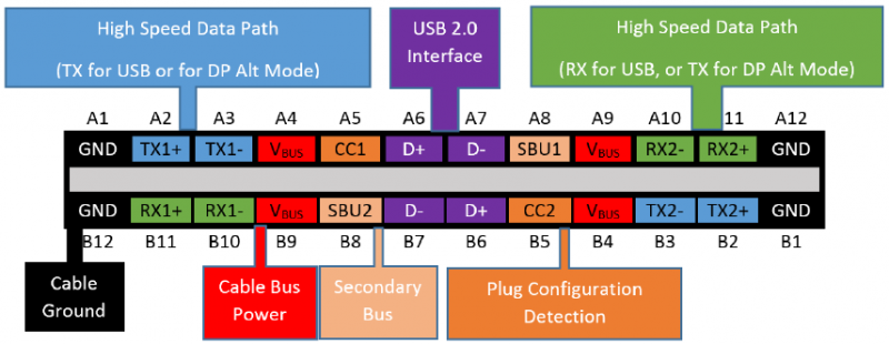
The USB-PD protocol instead travels through a single bidirectional “CC” line, that depending on the polarity of the connection, may end up being in either the A5 pin (CC1) or B5 pin (CC2). This communication is entirely independent of the primary USB protocol; many USB-PD devices, such as chargers, only implement the USB-PD standard with unconnected data lines. This CC line dares to communicate with devices no other line would dare to, such as the USB cable itself, in case of digitally marked for current-carrying capacities from 3 to 5 amps.
Power Flow
The direction of the power flow, in previous USB standards, was mainly determined by the type of connector (USB-A or USB-B), can now be actively negotiated through the USB-PD protocol. USB Type C connectors can be used for the host or client device, so each device may choose a role, either Source (the provider) or Sink (the consumer), when it comes to power.
The role may change during operation, depending on the specific application requirements; a representative example can be identified in popular USB hubs with the USB-PD “passthrough” feature: when plugged in the computer, the USB hub initially acts as a Sink. Subsequently, on the connection of an external power supply to the hub, a new power contract is negotiated between the devices, taking into consideration the capabilities of the power supply. Finally, the computer and hub swap their Source and Sink roles, with the computer now getting charged through the hub.
The role swap has received further improvements with revision 3.0 of the USB-PD protocol, following the introduction of the Fast Role Swap feature. Fast Role Swap allows devices such as laptops to take over the source role from HUBs in case of an AC power loss in under 150 microseconds, keeping hard drives and other sensible devices powered.
Depending on the revision of the USB-PD protocol adopted, either 2.0 or 3.0, sources can offer two modes of operation once the power contract is in place:
- Fixed Supply (USB-PD 2.0 and 3.0)
- Programmable Power Supply (PPS) (USB-PD 3.0 only)
In fixed supply mode, the source provides a fixed voltage of either 5V, 9V, 15V, or 20V. There is a maximum current based on the device’s power capability (Up to 5A and 100W) and the max current supported by the cable, from a standard baseline of 3A up to 5A.
In Programmable Power Supply mode, the source acts as a CV-CC (constant-voltage / constant-current) generator with configurable steps down to 20mV and 50mA intervals under the direct control of the Sink device. This leading-edge feature allows moving battery charging power circuitry outside of the sink device and into the source device, increasing efficiency and reducing the cost and dimension of the sink device. In addition to battery charging applications, it also allows a great deal of flexibility in your device—potentially allowing you to remove one or more voltage regulators from your device, offering cost savings in components as well as board space.
New in USB-PD 3.0
Additionally to the aforementioned Programmable Power Supply mode and Fast Role Swap, USB-PD 3.0 includes support for USB4, introduces communication of battery information between devices, introduces the USB-Type C Authentication protocol, and supports the newly announced USB PD Firmware Update standard. The latter may be of great interest to many electronic engineers, allowing for firmware updates through the USB-C connection similar to the USB DFU (Device Firmware Update) specifications. This can happen without the need for a complete USB device and the complication of having to enter DFU mode through user interaction, such as pressing a button for 10 seconds.
With other capabilities of the USB-C connector, such as USB-C Debug Accessory Mode, USB-C may be the only connector you need for both user interaction and product testing. This unification and expanded capability allows you to make further cost and space savings within your devices and simplify your production, further lowering costs.
Do you need USB Power Delivery?
The question haunting the dreams of every engineer adding a USB-C: do I need to add USB-PD support to my device, increasing the BOM lines with a USB-PD controller and satellite components? The answer may surprise you.
If all you need is a power source for your device and want to adopt a USB-C connector, you should consider your voltage, current, and power requirements.
USB-PD is the only official USB-IF (USB Implementers Forum) standard that will allow you to get voltages higher than 5V from a USB port. Qualcomm’s proprietary Quick Charge® standards are mainly relegated to the smartphone world, adopted by devices running on Qualcomm SoCs. However, the latest revision of Qualcomm’s Quick Charge® is fully USB-PD 3.0 compatible which leaves little justification for a Quick Charge implementation over (or in addition to) USB-PD unless you are using a Qualcomm processor which already has full support for Quick Charge.
If your device only has a limited voltage requirement of 5V, alternative standards may propose a viable solution, such as USB BC (Battery Charging) 1.2, which allows up to 2.4A draw. USB-PD allows your device to be fully USB BC 1.2 compatible if you wish to support both standards.
If you need the full 3A offered by USB-PD, but do not need voltages over 5V, TUSB321 from Texas Instruments may be the IC most indicated for your need at the time this article was written.
Available USB-PD Commercial Solutions
Implementing all the USB-C physical layer and protocol requirements from scratch would be a herculean feat and not something many engineers would be interested in doing unless their production volumes were incredibly high, to justify the engineering cost. Luckily, many silicon companies offer a broad portfolio of USB-PD ICs, with varying levels of integration and feature support.
Through Octopart's search features, we have found the following manufacturers offering USB-PD silicon, in alphabetical order:
- Analog Devices,
- Cypress Semiconductors,
- Dialog Semiconductor,
- Diodes inc,
- Microchip,
- NXP Semiconductors,
- On Semiconductor,
- Renesas,
- Rohm,
- ST Microelectronics,
- Texas Instrument.
Undoubtedly, this list is non-exhaustive, with manufacturers launching USB-PD products at an ever-increasing speed. With the new 3.0 standard, updated and additional products are being released at a rapid rate.
Here are a few USB-PD integrated circuits that have caught my interest recently. I bought dev kits for several of these to further evaluate how they can be used in my upcoming projects:
- STUSB4500: This IC is a popular and widely adopted solution for converting existing devices into USB-PD compatible sink. The IC does not require an external MCU, but you must use the I2C communication at least once during the first programming if you need a different voltage than 5V. A software called STSW-STUSB002 allows achieving this without writing a single line of code. If you want to connect it to an MCU, many open-source libraries are available on GitHub, such as ardnew/STUSB4500
- STUSB4700: Source-only USB-PD controller, similar to STUSB4500.
- STUSB1600: Base controller offer from ST. As the STUSB4500 and STUSB4700, it does not require an MCU.
- TPS65983B: Flagship USB-PD controller from Texas Instruments. This IC includes countless features out-of-the-box, including PD3.0 Fast Role Swap support, both Source and Sink support. While, at 120 pages, the datasheet may look intimidating, it sure is a stimulating read that reflects the profound contribution of Texas Instruments to the standard.
- FUSB302: If you have an I2C line to spare in your design, this minimalistic and affordable IC, part of ON Semiconductor portfolio, could be just what you need to add USB-PD source or sink capabilities to your design. It takes care of all the low-level communication.
- TUSB422: This USB-C controller from Texas Instruments has just 9 pins in a BGA package, perfect for space-constrained applications.
- STM32G0: STM32 Cortex M0+ MCUs that include a USB-PD controller. MCUs with integrated data and power have been announced for the second half of 2020.
- TUSB321: In case your USB-PD device needs only 5V (and thus, max 15W and 3A), this is the IC to choose. Doesn’t require an MCU and can be configured with just a few external resistors, keeping your BOM cost down.
Regardless of your IC choice, remember always to double-check you have added all the necessary TVS Diodes. They’re easy to forget, and a USB connector is probably the most likely place for an ESD event in your product!
Conclusion
Whether you are working on consumer products or bespoke equipment, the USB-PD standard might be just what you need to add versatile power capabilities to your devices. For me, USB Power Delivery 3.0’s ability to negotiate a very wide range of voltages allows me to build schematics powered by USB, despite requiring unconventional voltages.
The enormous wattage that is available on request can facilitate rapid charging of even large multi-cell lithium polymer battery packs without the need for a separate battery charger. You’ll see a new project from me related to this soon, which utilizes USB Power Delivery for rapidly charging a cinematography battery without an external charger. You can see an implementation of this in my Cinematography Battery Pack with Integrated Charging project.
While the implementation is undoubtedly more intricate than a modest DC connector, customers will surely appreciate using your product through the same connector they use for everything else. In addition to the cost savings from potentially not needing to supply a power adapter for your device, it’s becoming expected that a device can plug into a USB port for power, even if not for communications. Using USB Power Delivery could offer a level of future-proofing for your device, as well as convenience.
Would you like to find out more about how Altium can help you with your next PCB design? Speak to an expert at Altium.