USB Charger Project in Altium Designer: Part 2
In a previous blog post, I showed the process for building a schematic for a custom USB charger board using Altium Designer. This board requires a small number of components and some particular attention to the power supply design/decoupling networks, but aside from this it’s quite easy to build out the connections you need for the USB A connectors.
Here, I’ll show the strategy for translating this schematic into a compact board with a small form factor. Before getting started, take a look at the previous post on creating the schematic for this board. The general strategy for this board is as follows:
- Components on both sides: I’ll put components on each side of the board to save space on the surface layer. The component count is low enough that we won’t need to use the back layer or interior layers for routing.
- 2-layer or 4-layer board: I’ll build this on a 2-layer board, but you could certainly follow the steps shown here to build this on a 4-layer board with internal power and ground planes. If you opt for a 4-layer board, the only thing that will change is the trace width in order to ensure 50 Ohm single-ended impedance (90 Ohm differential impedance). There is some advantage to a 4-layer board in terms of natural EMI shielding from the conductive planes.
- Standard thickness board: Here, I’ll do everything on a standard 1.57 mm FR4 board for convenience. If you’re feeling creative, you could also do this layout on a thinner board or even a flex board as part of a larger system.
As was mentioned in the previous post, there are two differential pairs that need to be routed. We’ll take advantage of Altium’s differential pair routing tools to make these connections between the USB switches and the USB A connectors.
From Schematic to Layout
To get started with a new layout, add a new PCB document to your project and update the PCB document while in the schematic editor. Before creating the board outline and arranging components, you’ll need to define your stackup and configure your layers. Creating a stackup is rather easy, take a look at this article for guidance. When defining your layer stack, you can also create an impedance profile to determine the trace width you need for any controlled impedance tracks.
Layers, Board Shape, and 3D Body Placement
While in the PCB editor, press “L” on the keyboard to bring up the View Configuration window; this will show you the layers and view options. We need to set some mechanical layers, assembly layers, Courtyard layers, and 3D model layers:
- Layer 1: Board outline
- Layer 13/14: Assembly Top/Bottom layer pair
- Layer 1/16: Courtyards Top/Bottom layer pair
- Layer 5/6: 3D Top/Bottom layer pair
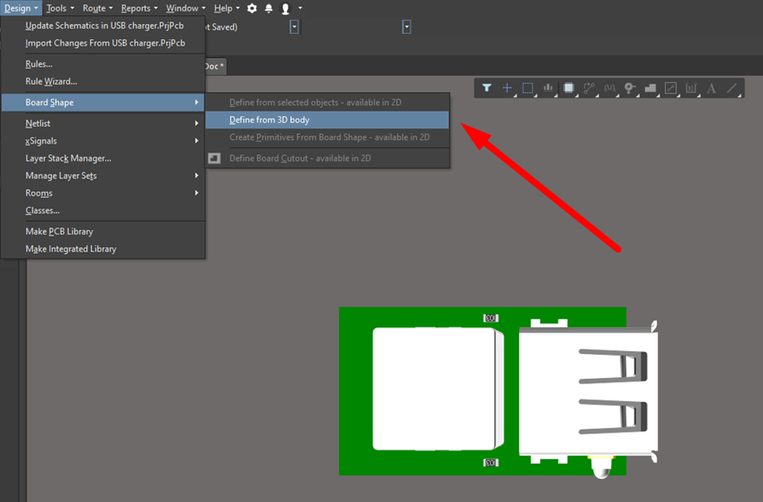
The next step before running through the layout is to place the USB-A connector body from a STEP file. Click Place → 3D Body and draw a simple 3D shape. Then, double-click the shape and set the model type to Generic, and load the required 3D STEP file. Note that the large box behind the USB-A connector (see below) is the inductor on the power supply feedback line (L1 in the schematic). Now, we can define the board shape directly from the 3D body to be sure we can accommodate the connector. The resulting board size is rectangular and measures 31.7 mm by 18.6 mm.
Time to Place Components
Usually, components that are close together in the schematic are placed close together in the PCB. You can prioritize placement by organizing the high speed or critical components to have the shortest trace lengths between them. Usually, the more time you take to place components, the less time you will need for routing. When you need to place components on the other side of layer, just double-click the component and you’ll see the Properties panel on the right edge of the PCB editor. You can set the precise location, layer, and footprint for each component in the Properties panel.
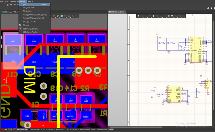
Because of the large size of the feedback inductor on the top layer, I’ll place everything on the bottom layer. The only passives that will appear on the top layer are resistors R12 and R13, and one of the LEDs. One easy way to keep track of all the components as they get arranged in the board is to use the Window → Tile command. This makes it super easy to cross-probe between the schematic and layout as you create the board.
Routing
Although space is cramped on the board, it’s easy to route with Altium’s interactive router. As you route the board, you can press the Tab key to change the trace width for that particular net and specific hole sizes. Regarding the power/ground lines, you should make the traces wider and the vias bigger. You can also press + or - while routing to change the active routing layer and automatically produce a via while routing traces.
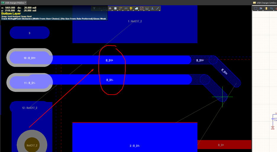
As was mentioned earlier, the traces leading from the TPS2549 output and into the USB-A connectors are differential pairs, so they need to be routed together. You can select Route → Interactive Differential Pair Routing to route these traces. If you did not define Differential Pair directives in your schematic, there’s no need to fret! You can still select the pads for these differential pairs and use the Route → Interactive Multi-routing command to route these signals.
Finally, the power and ground connections are defined using polygons, although you could also define them using mounting holes for other projects. After placing the polygon, the last step is to place silkscreen on the surface layers for component outlines and to designate power/ground/DIM connections and component reference designators for an assembler. Set only top/bottom silkscreen layers active or set only top/bottom silkscreen layers visible, then place all overlapped silkscreen labels on the proper position. The final silkscreen for the top layer is shown below.
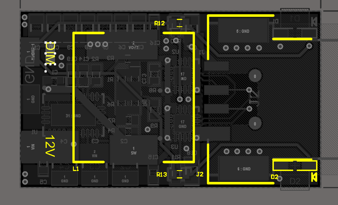
After running a final DRC check, this board is finished! It looks great in 3D view and it has a small footprint. The system shown here is simple enough that it could easily be brought into another project with minor modifications. If you’re interested in obtaining the design files for this project, send me an email at zmp@nwengineeringllc.com, or find me on LinkedIn.
Whether you are creating a USB charger project like the one shown here, or you’re creating advanced digital or high frequency systems, the full suite of CAD features in Altium Designer® are ideal for your next project. The powerful PCB design platform in Altium Designer gives you access to all the design tools you need for this project and many others in a single application. You’ll also have access to a full set of simulation, data management, and production planning tools.
Now you can download a free trial of Altium Designer and learn more about the industry’s best layout, simulation, and production planning tools. Talk to an Altium expert today to learn more.
