RGB + White LED Strip Controller
I’ve been playing around with RGB LED strips recently for lighting up my test equipment rack as well as some display shelves. On the display shelves, I have the RGB LED strips behind the shelves, which gives a great definition to the objects on the shelf. But I also want to have a high CRI white LED strip on each shelf to light up the objects. Typical RGBW LED strips available through online marketplaces do not have very good white LEDs, and I’m not looking for an integrated LED strip. I can’t find a low cost LED strip controller that would drive RGBW strips, nevermind a separate white LED strip.
I’ve built a few LED drivers as projects in the past, but that’s not what we need here. We don’t need to provide a constant current to an LED strip, as they have current limiting resistors on each diode. All we need to do is provide power and a PWM signal to each coloured diode to get the desired blend. I want this to be relatively simple and cheap, and the infrared remote controls that can be purchased incredibly cheaply through online marketplaces such as Amazon and eBay are great for LED strips. These are much more convenient than having to write a mobile app to use Bluetooth or WiFi to control the LED strips.
A full roll of the very low-cost strip I purchased only consumes about 0.5A per colour at full power. I know that a better RGB LED strip would need higher current — so I want this controller to be capable of at least a couple of amps per channel. My high CRI white strip certainly pulls far more current than the RGB! Every RGB strip I’ve ever purchased has been a common anode configuration, which is fantastic as it allows us to use a low resistance N-Channel MOSFET for switching the colours.
As we need four identical drivers, this is a fantastic chance to demonstrate one of my favorite time-saving features in Altium: multi-channel design.
As always, you can find this project with all my others on GitHub, released under the permissive MIT open source license. You can find the components used for this project in my free open source Celestial Altium Library.
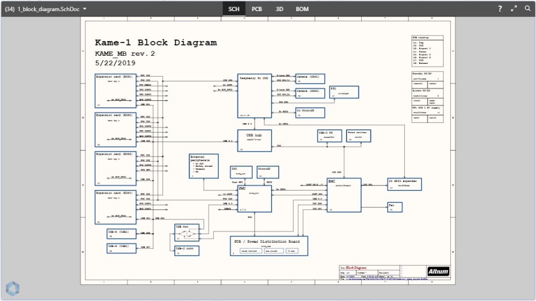
Above is the PCB design you'll be reading about in the Altium 365 Viewer; a free way to connect with your co-workers, clients, and friends with the ability to view the design or download with the single click of a button! Upload your design in a matter of seconds and have an interactive way to take an in-depth look without any bulky software or computer power.
Schematic Overview
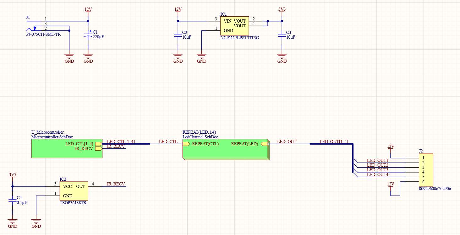
To use multi-channel functionality, we’ll need a hierarchical schematic. My top sheet has my connectors, and since its such a simple project, it also has my voltage regulator and the IR receiver.
Microcontroller
Despite being a 4-channel LED controller, we only have two other schematic sheets. Firstly, we have the microcontroller. I’m using an NXP LPC11Uxx series microcontroller. I’ve used these in past projects because they are quick and easy to develop code for using MBED or LPCOpen, and I have a well-proven schematic for utilising the MCU.
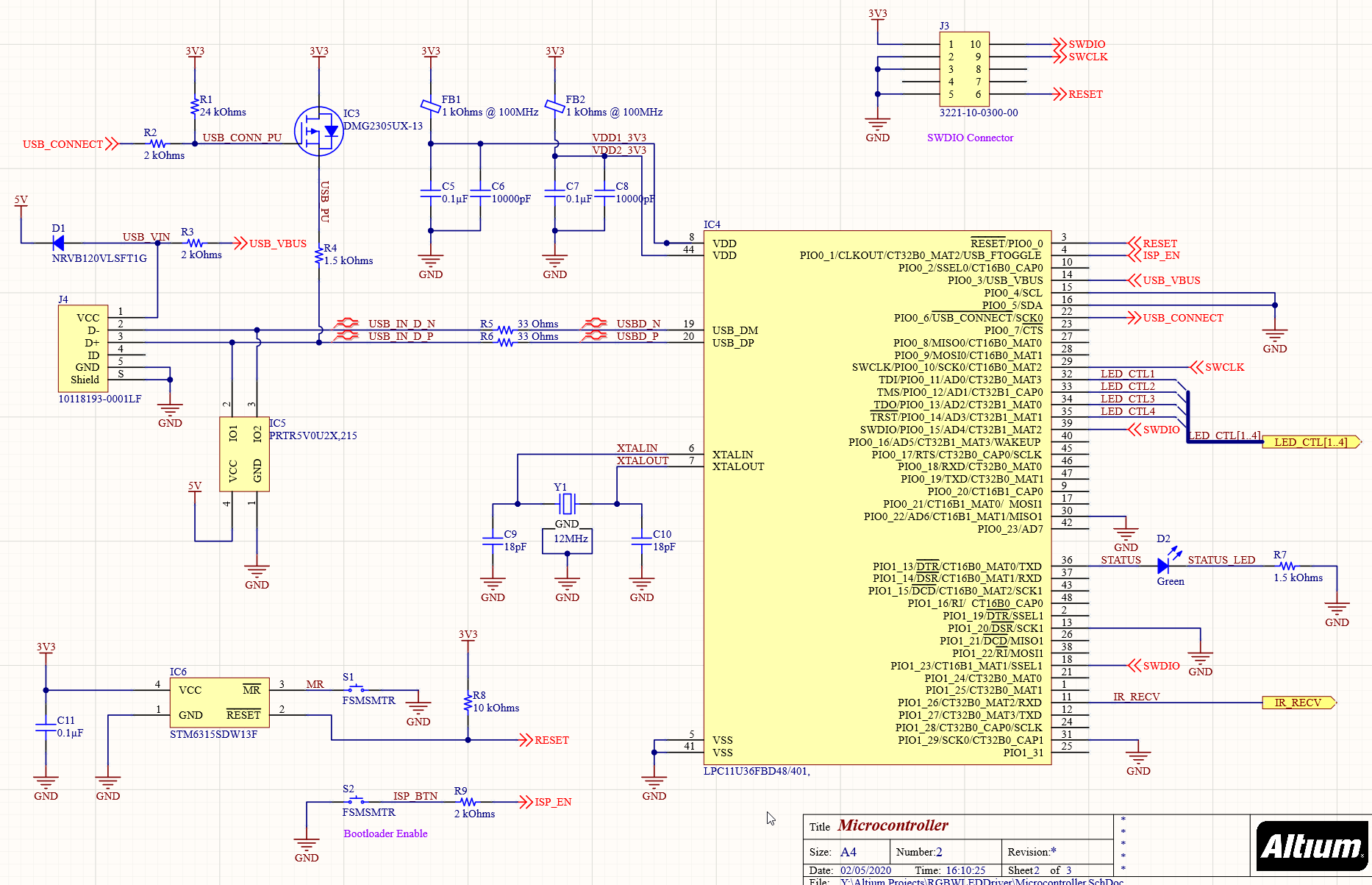
The part of the microcontroller schematic of most interest to us is the LED bus.
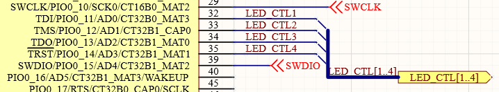
It’s a simple bus with Bus Entries to each net on the microcontroller. Note that we start our channel numbers at 1, rather than 0 as you might typically see. Multi-channel buses must start with 1. As this is a multi-sheet schematic, we could name the nets in each sheet whatever we want, but I like to try to keep the same net names across sheets where they will connect, just to preserve my sanity when looking through different sheets.
LED Channel
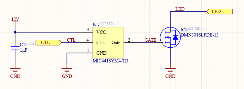
We only have one schematic sheet with just a single driver and MOSFET for all the LED channels.
With the multi-channel capabilities, we could use one schematic sheet with the single driver/MOSFET on it for any number of channels, all of which would be identical, and any changes made applied to all channels.
I have a very simple gate driver in the schematic to ensure the MOSFET reaches its minimum switched on resistance, the 3.3V from the microcontroller isn’t going to make that happen. Additionally, my test equipment rack is in the background of video shots, so I want to ensure the PWM frequency I use for it will be quite high, so there is no banding or flicker in the video. The gate charge on the MOSFET is not very high. Still, the drive current available from the microcontroller is fairly limited, so having a driver ensures that both the on-resistance is minimised and that I don’t burn out the microcontroller pin.
Multi-Channel Configuration
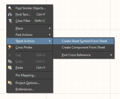
Firstly, we need to create a sheet symbol from the LED channel schematic sheet. We could do this by placing a sheet symbol on the top-level schematic and then linking it to the LED channel sheet, then add the ports… or we can take the easy route by right-clicking on the top-level sheet and selecting Sheet Actions → Create Sheet Symbol From Sheet.
This gives us a basic sheet symbol, which is a single LED channel.
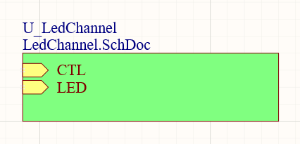
Instead, I need 4 channels to program this symbol by renaming it REPEAT(LED,1,4). LED is the name each channel will start with. The 1 is my starting channel number, and 4 is the end channel number. This matches up with my bus pin naming.
We also need to add REPEAT to the ports' names on the symbol, so each channel will get its own connection on the bus for those ports. If you had something like an SPI bus, you would only REPEAT the chip select (CS) pin, with the other ports (MOSI/MISO/SCLK) being common between the channels. This offers a lot of flexibility to multichannel design.
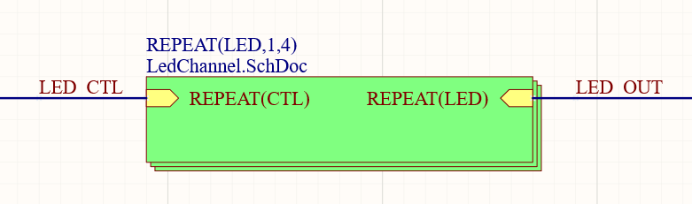
Because these are ports for a single net per channel and not a bus, we need to use a regular net wire to connect them. This should have a netlabel with the same name as the bus, just without the pin information.
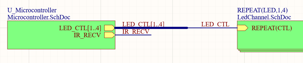
This allows us to connect the bus of pins with the same numbers as each channel into the channels from the microcontroller. The microcontroller port is labelled as a bus, and needs to have a bus connection coming from it and into the wire for the channel. It can take a little bit of time to wrap your head around the idea of the busses and nets for these repeated ports/channels. I find the best way to think of it is to consider the port function for each repeated channel rather than the multi-channel block itself.
Board Layout
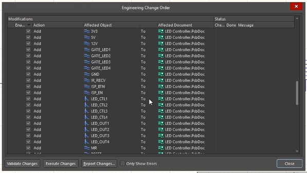
You can verify your multi-channel design has been configured correctly when you go to update your PCB document. The engineering change order will have multiples of each net that is in the channel, as you can see below with the GATE_LED, LED_CTL, LED_OUT nets, and bus entries. You’ll also see multiple components for each net in the change order and, most importantly, multiple rooms.
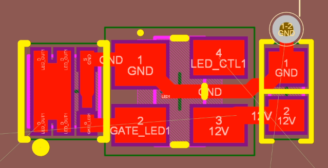
We can now layout a single channel of the LED within its room and minimise the room size to just larger than the components. For an application like this, where the channels are going to be very tightly spaced, keeping the room size as small as possible is important. By default, Altium will assign components, vias, and tracks to a room based on if they are within the room boundaries or not. To avoid frustration when rearranging rooms as you work on your layout, you want to minimise the room size so Altium won’t drag tracks or vias from an adjacent channel because those objects are within the room you are dragging.
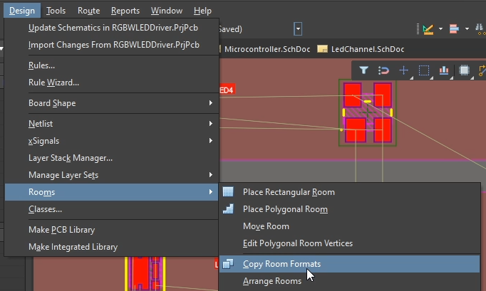
To apply this same layout and routing to all the other channels, we can go to Design → Rooms → Copy Room Formats.
Then select the room that was laid out and routed as the template, followed by another room in the channel.
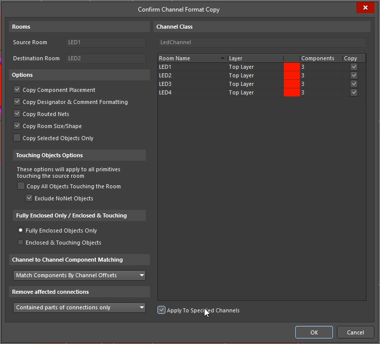
If you select the Apply to Specified Channels box, it will automatically apply the template to every room within the template, allowing you to layout and route potentially hundreds of channels in a single click. If you were building a device with a lot of identical input or output channels, this is an incredible time-saver, especially with critical routing such as analog instrumentation signals.
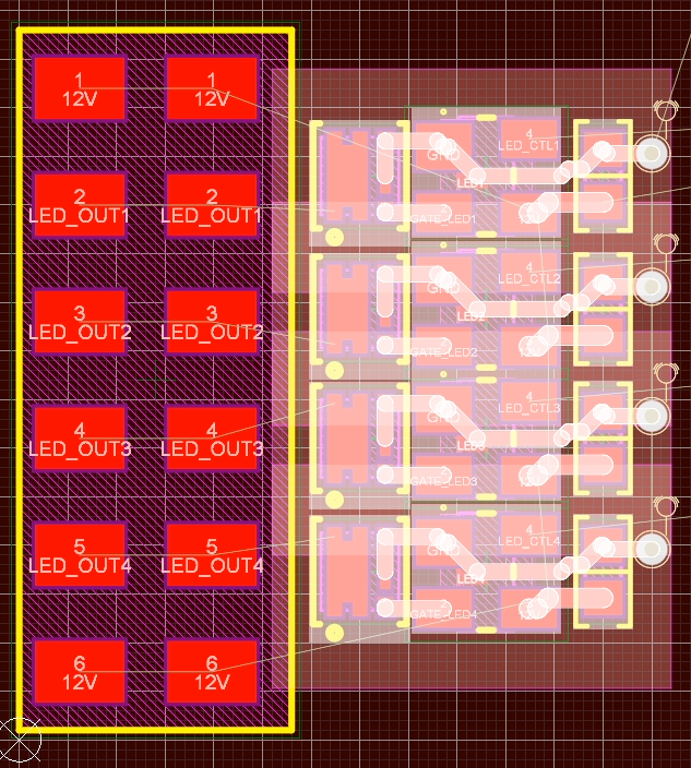
With just a little more work, our multiple LED channels are aligned with the connector.
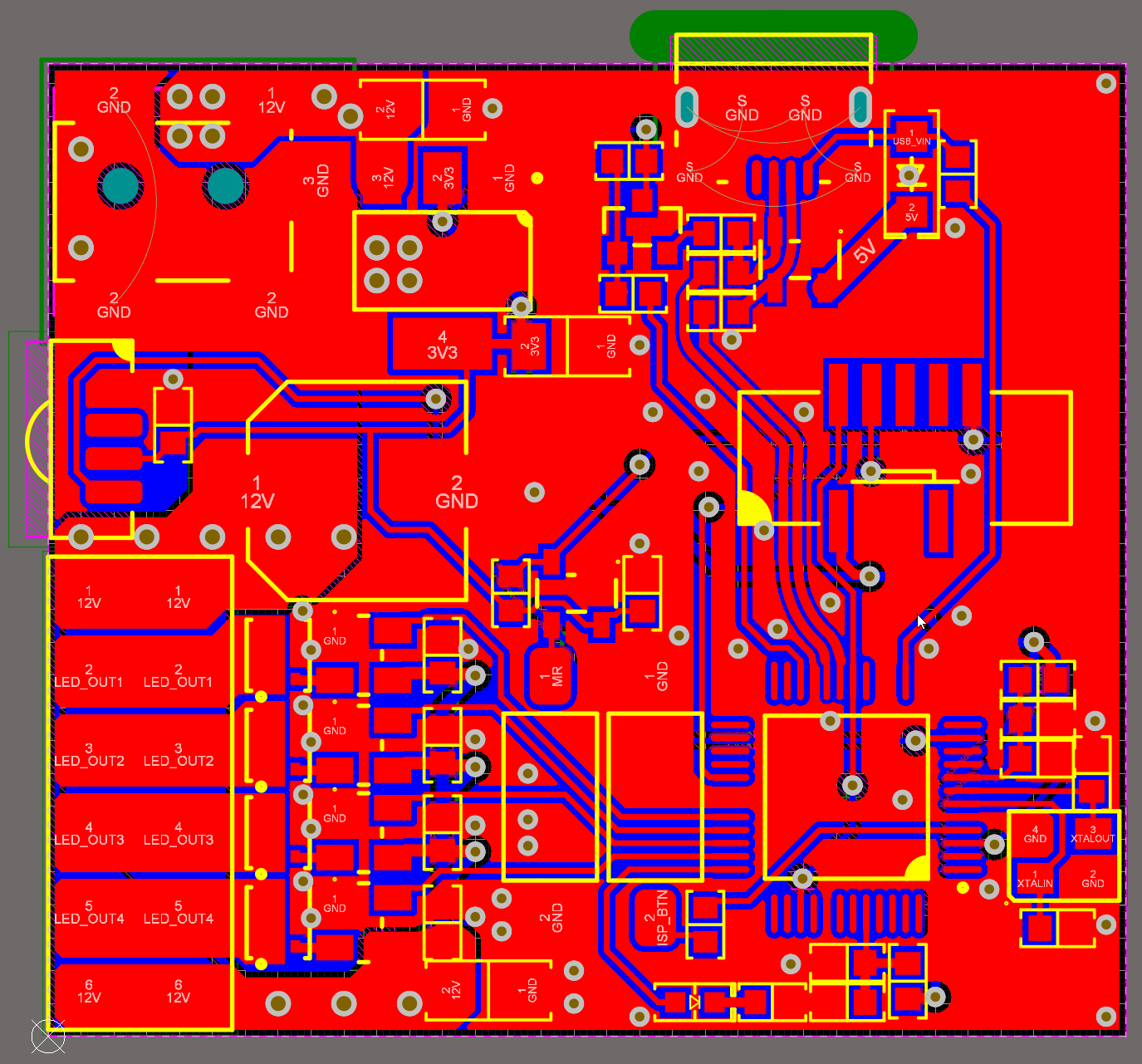
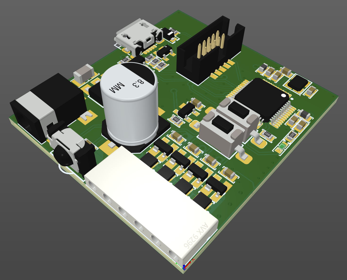
Finished Board
To finish off the channel routings, I added polygons between the MOSFET and the connector. The rest of the board is pretty typical routing. I connected several of the unused microcontroller pins to ground to facilitate ground pour continuity across the board.
Even with my low cost LED strip, we would still have 1.5A of current draw from the 12V input to the RGB channels, so there does need to be some consideration for current paths. Adding in the high brightness, high CRI LED strip we increase that draw further - and with some better quality LED strip, the total draw of the board is more than enough to have some consideration for the layout.
I have a large bulk capacitor at the 12V pin for the RGB strip, and a smaller capacitor for the white channel to reduce switching noise from the channels getting dimmed or colour mixed.
The finished board is a great size for me to hide away somewhere yet still have the IR receiver able to receive a signal from the remote. With no components on the bottom and no clearance issues with connectors, I can simply add some sticky-backed velcro to the bottom of the board for mounting.
Finally
As mentioned at the beginning of the article, you can find this project on GitHub. The design and all of its files are released under the MIT license for you to do with as you wish.
Check more of Mark Harris’s projects using Altium Designer. Would you like to find out more about how Altium can help you with your next PCB design? Talk to an expert at Altium and learn more about making design decisions with ease and confidence.