Modeling Capacitor Impedance Vs. Frequency Using an Excel Spreadsheet
As noted in an earlier article, based on class notes from our two-day design course, getting the power subsystem design correct is the most challenging aspect of today’s high-speed PCB design process. A major aspect of this process is modeling the power supply to ensure that it will function properly in the end product. A critical part of this modeling effort focuses on being able to model capacitor impedance vs frequency. This is simple enough that it can be done with an Excel spreadsheet.
This article will describe how the capacitor population is chosen, how an Excel spreadsheet can be used as part of this effort, how a SPICE model for analyzing the capacitors is created, and how close the resulting predictions are to a real circuit and the elements in a complete PDN. Highlighted in this article will be the PDN tool from Altera, which is available free of charge.
What Governs Capacitor Impedance vs. Frequency?
Before drilling down into the topic of how to model capacitor impedance vs. frequency using an Excel spreadsheet, it’s important to understand how a capacitor behaves.
There are three elements in a capacitor, and they consist of:
- The capacitor itself.
- The inductance of the capacitor and the mounting leads.
- The resistance of the conductors.
The foregoing elements occur in series, and an RF engineer would label the resulting device as a series of tuned circuits.
Understanding how the capacitor behaves is based on the following criteria:
- At low frequencies, the impedance is very high, so the capacitor’s behavior is not visible.
- At high frequencies, the capacitor acts as an inductor.
Figure 1 shows the impedance versus frequency for two common capacitors.
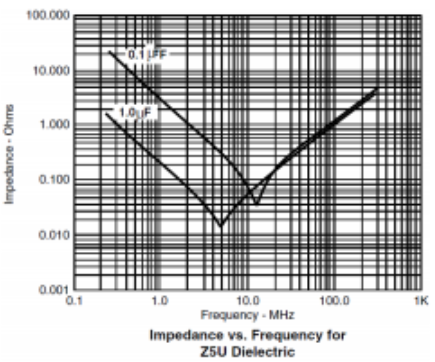
At low frequencies, the impedance of the capacitor is as one would expect. Eventually, the parasitic inductive reactance and capacitive reactance at one frequency are equal and cancel each other, just like in an LC circuit at resonance. At the bottom of the graph, the impedance of the capacitor is just equal to the ESR (equivalent series resistance).
Note: ESR is a parasitic resistance in all components due to the finite electrical conductivity of the conductors from which component leads are made.
Groups of capacitors can exhibit series and parallel resonances, where the resonances depend on how the capacitors are laid out in a circuit. Each resonance occurs when the impedance at a certain frequency (or frequencies) is minimized. Around a resonance frequency, the capacitor is most useful in the power supply, but it is only useful across a fairly narrow range of frequencies. Broadening the useful frequencies over a broader range is one reason multiple capacitors are used in a PDN.
Proper Impedance Calculations
As noted previously, product developers don’t always know the exact distribution of frequencies that ICs on a PCB will require. As a result, the impedance of the PDN has to be made low from DC to some value up to many hundreds of MHz to ensure high frequency voltage ripple on the PDN is within acceptable limits. In order to accomplish this, multiple capacitors with different values are chosen. These capacitors interact with each other to produce a complex set of resonances (impedance minima) and anti-resonances (impedance maxima).
To calculate the overall impedance of the PDN, an Excel spreadsheet can be used to create the PDN impedance vs frequency for a set of capacitors, as shown in Figure 2.
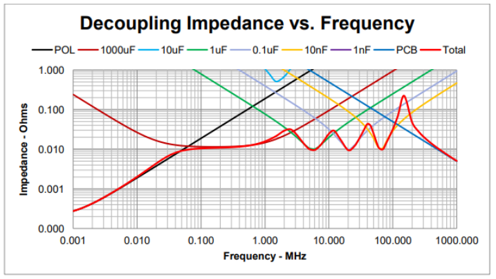
A few things to keep in mind as you go through this process.
- The impedance of an inductor goes up as the frequency goes up.
- When a regulator stops regulating, it looks like an inductor.
- The black line in Figure 2 is the inductance of the regulator. All of the lines that go up in this manner are inductors.
The heavy red curve in Figure 2 is the overall impedance that results from selecting the capacitor population highlighted in Figure 3.
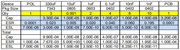
This information includes the types and quantities of capacitors that were ultimately chosen for a Speeding Edge consulting project. For this project, it should be noted that it was necessary to achieve 10 mOhms from DC out to nearly 100 MHz.
As Lee Ritchey, Founder and President of Speeding Edge notes, “People think that a board like this requires thousands of capacitors. If we had just relied on the IC supplier’s application notes, we would have used ten times as many capacitors, and they would have been of the wrong values.”
It should be noted that using the previous method to calculate overall PDN impedance does not take into account the interaction between the parasitic inductance of the capacitors and the plane capacitance of the PCB. To get this information, a SPICE model of a field-solver based model must be constructed. Figure 4 is the spice model used for analyzing bypass capacitors in a PDN.
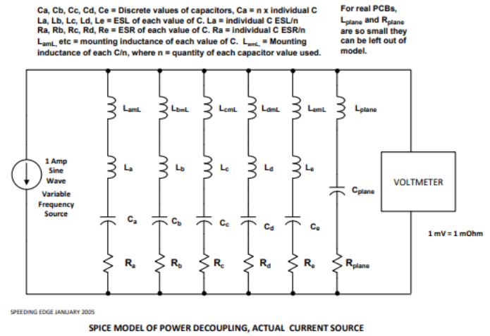
Figure 5 is the model of a whole power supply. This model shows the series R, C, and L values of the part, and the inductance of the mounting.
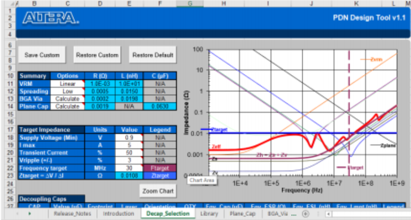
The image in Figure 5 is from the Altera PDN_TOOL_V10 spreadsheet. With this tool, you can define the shape of the plane, how big it is, how far apart the planes are, what the dielectric constant is, and how far down the board is. Once the parts are selected and the defined geometries, the tool calculates all of the inductances. For input, the tool requires the user define delta(I) (change in current), and the allowable ripple should be specified. This will give the target impedance and then, based on this information, capacitors that will get close to achieving whatever target impedance can be selected.
The math inside the spreadsheet accounts for the fact that the capacitors interact with each other. There are sophisticated, commercially available tools that will also perform the preceding analyses and design tasks and even create 3-D models if needed. However, Altera’s spreadsheet will sufficiently satisfy the needs of most product developers.
Summary
Getting the design of a working PDN nailed down is one of the most challenging aspects of PCB product development, and selecting the right capacitors is an integral part of that effort. Determining the correct values and ensuring that they are close to the target impedance goes a long way towards creating a PDN that works as designed.
Talk to an Altium expert today to learn more or continue reading for in-depth information on component models' data management in SPICE simulations.