Know the Power Dissipation
Understanding power dissipation of an individual component, an electrical block, or even the whole electronics system is essential for electronics engineers. It is important not only to avoid exceeding the maximum limits of components but also to calculate unknown parameters in input or output sides because power dissipation is related to system voltage and current. In this article, I describe my practices for analyzing power dissipation in electronics designs.
Very basics
First, I’ll go through the basics of power dissipation on which all my analysis methods are based. The first rule relating to power is as follows: Input power of the system is always bigger than output power, and it can never be vice versa, i.e. There is always some power loss (Ploss) in components, and this is its power dissipation. Power dissipation is then Pin – Pout.
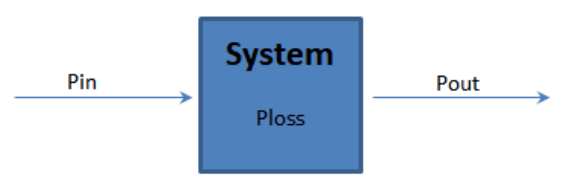
The basic power dissipation flow is presented in Picture 1. If we input power to the system, a part of that power is lost inside the system to heat, and the output power is reduced. Thus output power must be less than the input power.
Most of the power loss eventually becomes heat inside a component; this is typically thought to be power dissipation. In the case of active components, part of whole power may be transferred to other energy forms, which is generally considered power consumption. For example, in LEDs, power consists of emitted light (power consumption) and heat (power dissipation). So power dissipation is heat, and power consumption is the power we wanted to get out of the system. In power dissipation analysis, we don’t analyze power transfer, for example, from electricity to light, but only how much the system or a component dissipates power.
The second rule is the relationship of electrical power to voltage and current. As we know, it is added voltage multiplied by the current consumption of a system, i.e. P = UI. The relationship between voltage and current is resistance or impedance, which is the familiar ohm’s law U = RI or U = ZI. With these two equations and their combinations, we do all of the following power dissipation calculations. It is good to remember these laws are always valid. We have exactly the same electrical power if an added voltage is 5V, and the current is 1A through 5Ω resistor, or added voltage is 1V, but current consumption is 5A through 0.2Ω resistor. In both cases, power dissipation is 5W, regardless of whether we calculate it using voltage and current or current and resistance. In current based calculations, we get P = RI², with P = 5Ω*1A² = 5W or P = 0.2Ω*5A² = 5W.
The third important parameter in power dissipation analysis is efficiency, ƞ. Efficiency indicates how well energy is transferred from input to output.
- ƞ = Pout/ Pin
Because output power is always less than the input power, efficiency is always less than 1. Many ”power” components’ data sheets provide efficiency, and with this number, we can estimate the amount of power transferred from input to output and thus calculate voltage and current levels. The fourth important item to know is which one is changing in the system; is it voltage, current, or both? Typically, passive components and LEDs are “systems” in which voltage changes from input to output, but the current remains the same. In active systems, either current or voltage or even both may change. For example, switching converters typically have different voltages and currents in input compared to output.
Average or peak power dissipation?
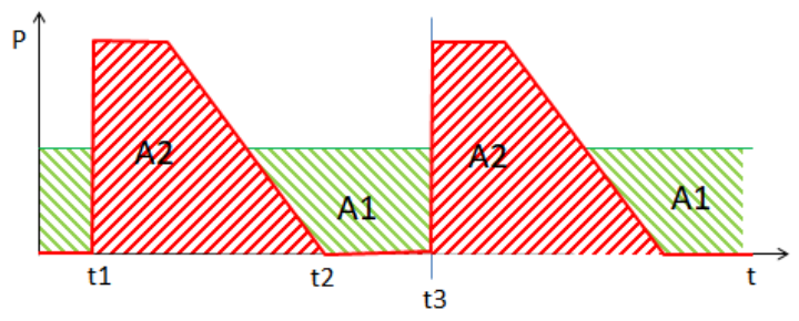
Often, power dissipation is not constant but varies over time, periodically. In these situations, we still use the same principles to analyze power dissipation, but we have to understand what to calculate. If we draw power dissipation as a function of time for average and peak power dissipation, we get something similar to what is presented in picture 2. Average power dissipation is constant over time, but with variable power dissipation, we see power peaks in the graph. Power dissipation is a time integral of a period [1], [2], and for cases in Picture 2, power dissipation is where T = t3.
In practice, an integral calculates the area, which is limited by power curves. In Picture 2, altering power dissipation is A2, and constant power dissipation is A1. If both power dissipations are measured from the same device, the integral calculation gives the same result for both cases, such that the area of A2 is equal to the area of A1.
When analyzing power dissipation, we need to understand how to take the alternating power dissipation into account during our calculations. Averaging sums all power dissipated in a period and distributes it equally within that period. Peak power dissipation is the maximum power dissipation at a specific moment, i.e. maximum of p(t) in equation (1) [1]. Average power dissipation includes peak power dissipation, but also moments when power dissipation is smaller or zero. Thus average power dissipation is useful when we are interested in the power which heats the component. Peak power dissipation is useful when we are using it for analyzing current and voltage peaks. According to reference [3], some multimeters measure in AC mode Root Mean Square (RMS) of a signal, and this value has a direct relation to average power dissipation. References [1] & [2] show how average power dissipation correlates to RMS measured AC signals, and this relation is:
- Pᴬⱽᴱ = Iᴿᴹˢ * Uᴿᴹˢ
If we calculate average power dissipation, we can verify calculations just by measuring alternating currents and voltages using multimeter AC settings. Of course, if we know we have DC conditions in our system, we need to measure current and voltage in DC mode.
Analyzing Power Dissipation: Voltage Changes – Current Constant
The first example is simple but applicable for all electronics engineers: LDO regulator. These regulators can model similar to picture 3. We can also quickly determine that the input current and output current are nearly the same, but voltages differ between input and output. For very small current consumption systems, the quiescent current of LDO becomes important, but if the output current is relatively much bigger than quiescent current, we can ignore it.
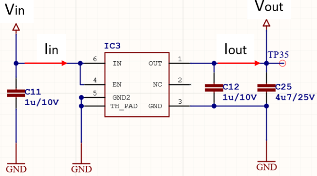
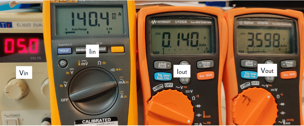
In this example we have 5V input voltage, 3.6V regulated output voltage, and 140mA output DC current. The power dissipation calculation for this LDO is the following:
- Ploss = Pin – Pout
- = Vin * In - Vout * Iout
- = 5V*0.14A - 3.6V*0.14A
- = 0.7W – 0.504W
- = 0.196W
Efficiency is then
- ƞ = 0.504W/0.7W = 0.72
In picture 4 we can see real measurement results for this example LDO. We see current input and output are the same, and voltage input and output are different.
We see the critical parameter, from a power dissipation point-of-view, in current constant systems is the voltage difference between input and output. For those, you must carefully analyze the voltage drop in relation to the current and notice it is ending up as heat. You must make sure the selected component can stand calculated power dissipation and design it for 80% of the data sheet maximum. Similarly, we can analyze the power dissipation of passive components, LEDs, diodes, transistors, etc.
Analyzing Power Dissipation: Voltage and Current Changes
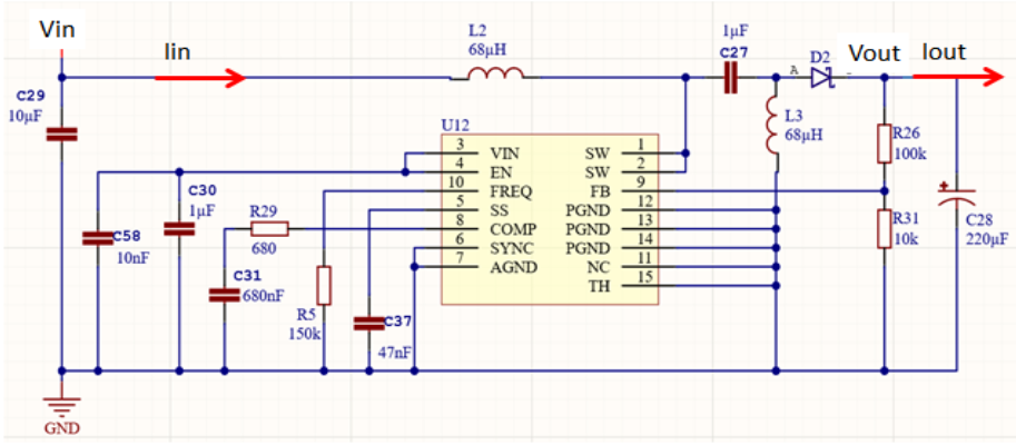
Our second example is more complicated: a switching regulator. A buck-boost converter, presented in picture 5, is a system in which both voltage and current change. In this example, the input voltage range is 10V to 20V, the input current is unknown as it depends on the input voltage as well, and the designed output voltage is fixed to 13.5V and required output load current is 80mA.
We start analyzing power dissipation by first estimating the input current that the converter takes in. For this, we utilize ohm’s law-based power and efficiency calculations. Converter output power is
- Pout = Vout* Iout
For this, we add the efficiency equation and get
- Vout * Iout = ƞ * Pin
Continuing the calculations using real numbers (Vin 20V) presented earlier, we get:
- 13.5V*0.08A = ƞ * 20V* Iin
- 1.08W = ƞ * 20V* Iin
We have two unknown parameters, and from the switching converter datasheet, we need to check the efficiency for used voltage and current ranges. In this case, it is approximately ƞ = 0.85. Now we can calculate the input current of our switching regulator:
- Iin = 1.08W/(0.85*20V) = 64mA
Now we have all parameters for calculating power dissipation of the switching converter, and get:
- Ploss = Pin – Pout = 0.064A*20V – 0.08A*13.5V = 1.28W – 1.08W = 0.2W
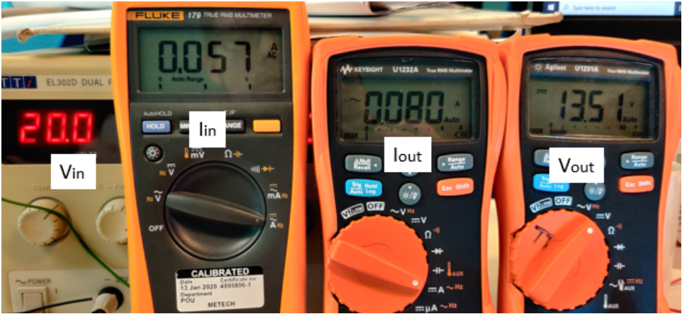
A real measurement proves that the calculations are correct, as shown in picture 6. We see efficiency in this actual sample is slightly better than in our calculations, but overall we see this analysis model is entirely accurate.
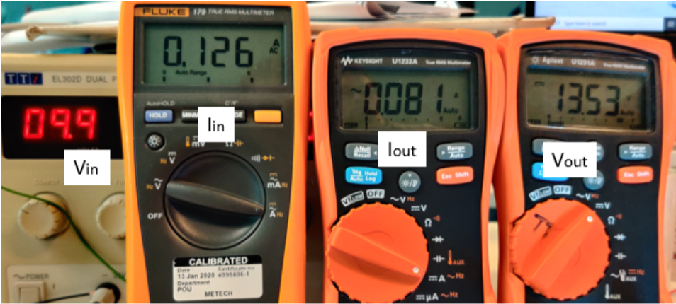
In the same way we can calculate power dissipation in boost mode, we can see again the correlation between our calculation and real measurements as presented in picture 7. Now, the analyzed input current is
- Iin = 13.5V*0.08A / 0.85*10V = 0.129A
Power dissipation in boost mode is then:
- Ploss = Pin – Pout = 0.129A*10V – 0.08A*13.5V = 1.29W – 1.08W = 0.21W
The switching converter is an example of the power dissipation of an electrical block power. It doesn’t consider power dissipation of individual components, only the power dissipation of a whole system.
What to analyze?
Power dissipation has a close relationship with the heating of a component, and it is important to calculate in all components we recognize as critical. These components can be voltage regulators, transistors, diodes, LEDs, and passives. For critical components, we must check at the least extreme maximum condition, which typically happens when RMS current consumption is the maximum. We need to compare the calculated maximum value to the component’s maximum and make sure this is not exceeded in any cases during the product’s normal operation.
Secondly, we need to analyze the power dissipation of critical electronics blocks, like switching converters, driver circuits, and power stages. For these, we can utilize power dissipation calculations as basic design work, as we saw in the switching converter example. Also, calculated power dissipation is worth comparing to datasheet values, but individual component selections for electronics blocks should be based on design and simulations.
Also, we need to analyze the whole electronics system power dissipation. We need to sum together all calculated power dissipations of electronics blocks and compare it to power supply capabilities. In that way, we can ensure our power supply can provide the required power for the device within the whole supply voltage range.
Last but not least, we need to remember that most of this power dissipation becomes heat, and we need to analyze whether electronics require additional cooling, or whether we can live with it.
References
[1] Joe Wolfe, RMS and power in single and three phase AC circuits, Web article in University of New South Wales, Sydney, Australia.
[2] Freddy Alferink, Theory and definitions: Energy and power.
[3] Blog in Fluke website: What is true-RMS?