Isolated vs Non-Isolated Power Supplies: The Right Choice Without Fail
There may come a time in your career as a PCB designer when you must adhere to regulatory requirements. Whether it be medical, automotive, military, or anything of the sorts, your design will certainly be scrutinized and held to very high standards.Oftentimes, when these regulations are in effect, power isolation (or lack thereof) is a very popular topic.
What is power isolation, and what is an isolated power supply? Power isolation is essentially what it sounds like: the power supply is isolated from the rest of the applied circuit. This is common among these agencies for obvious reasons, especially in the medical field. With a non-isolated power supply powering your medical PCB, there is a greater risk for dangerous shocks to surge through the supply and into your device, potentially harming the user (and maybe even the patient!). Yikes!
An understanding of isolated vs. non-isolated power supplies is all about designer and user safety. Here, we're not talking about the AC or DC power supply units you find the lab. For many power electronics systems and embedded systems, the power supply is integrated into the board, and it doesn't appear as a single integrated circuit. Power supply isolation, even when integrated into the board, is required to protect the end user and equipment. So let’s all do ourselves a favor, and consider the difference between an isolated vs. non-isolated power supply before starting your design.
What is an Isolated Power Supply?
An isolated power supply is a power supply that is electrically isolated from the rest of the circuit that it is powering, often by an isolation transformer. This means that power and voltage is transferred from the input to the output without a direct electrical connection between the two sections. These power supplies can accept a large input voltage from AC mains and convert the input down to a lower voltage. Subsequent PFC and regulator stages are used to limit the output current to a stable value, which ensures the downstream components are protected from large voltage and current surges at the power supply input.
For a lab-grade DC or AC power supply, the user will need to interact with the output stage of the isolated power supply. In other words, they may need to plug or unplug wires, adjust some settings on the front panel, or otherwise handle the power supply unit. By isolating the input from the output, the end user of the power supply is at lower risk of shock when they work with the power supply. A typical topology for converting AC to DC with an isolated power supply is shown below.
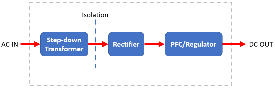
Simple topology for the output stage of an isolated power supply via an isolation transformer.
For DC-DC conversion, an isolated power supply requires first converting high power DC to an AC signal (such as with a resonant LLC converter), which is then stepped down to a lower voltage with a transformer. The rectifier/regulator stages shown above then convert the new AC power voltage on the output side to DC power. More complex designs, such as a flyback converter or other isolated switching DC-DC converter, will use a switching MOSFET to generate a time-varying waveform, which is then stepped-down on the output side and regulated.
Transformers Provide Galvanic Isolation
An isolated power supply uses an isolation transformer to provide galvanic isolation between the input and output sections. Transformers simply transfer power between coils using the magnetic field generated by an alternating current in a solenoid, and the voltage is stepped either up or down, depending on your downstream power needs. The benefit of isolation with a transformer is that there is no direct electrical connection between the input and output coils on the transformer; the conductors on each side do not touch each other. Power is only transferred between the coils via induction. This keeps anything downstream of the transformer protected from high voltage/current on the input side, or, in other words, ‘isolated.’
When a feedback loop is needed for monitoring and control over the output power, an opto-isolator is normally used to link the output back to an earlier regulator stage. This component uses an infrared diode to ensure isolation between high power and low power regulator stages. For power supplies that run at low voltage / current, an opto-isolator can usually be connected directly to the output, although there are some opto-isolator ICs that can receive larger voltage / current levels.
One point to consider in an isolated power supply is its efficiency. All transformers have some losses, both in the form of heat dissipated in the winding and due to alternating magnetization in the core. The magnetic material used in the core (usually iron or a ferromagnetic alloy of iron) becomes magnetized back-and-forth as the input AC current oscillates. When the magnetic field created by the AC input is very large, it can cause magnetization in the core to saturate, which limits the output power (decreases efficiency) and creates greater core losses.
This type of transformer might be found in a large isolated power supply.
Isolated vs. Non-Isolated Power Supply
Now that we know what isolates a supply from your board, it becomes rather obvious that taking the transformer out of the design chain suddenly makes it a non-isolated power supply. Designing a board without power isolation is a common practice especially outside of the regulatory agencies, however I still urge you to consider the end-user along your design journey, as you might just save yourself a court case or two when your supply hits the fan and gives your favorite customer a shock they won’t soon forget.
The upsides of designing these non-isolated power designs are plentiful. First, you’ll enjoy more board space relative to an isolated power supply design due to the fact that you won’t need to put a big transformer in your enclosure. You'll also benefit from increased efficiency with a non-isolated power supply.
Non-Isolated supplies always hold the risk of electrical shock through the design.
It is worth noting that it is common practice to place non-isolated supplies downstream of an isolated supply (sometimes physically separate from each other). In this strategy, the isolated power supply is placed at the high power AC or DC source, which then drops the voltage down to a level that is safe enough for a standard DC regulator IC or circuit. This is a bit more complex, but it has the advantage of giving you the proper protection that checks off your safety requirements. An example of this may look like a standalone medical power supply (isolated) that feeds a handful of devices (non-isolated) downstream.
So Which One Is Right For You?
As previously stated, isolated power supplies are often required for regulated industries. Examples include the IEC 60601-1 safety standard for medical devices, IEC 62368-1 for IT and AV equipment (replaces IEC 60950-1 and IEC 60065), and IEC 61204-7:2016 for general switched-mode power supplies.
After the facts, benefits, and applications are presented, do you know which one is right for your application? Keep in mind that creating an isolated power supply on your board will take up some board space and it will be slightly less efficient, but it protects the end user from electric shock and it can easily feed power into a non-isolated supply.
If you've decided on an isolated vs. non-isolated power supply for your next system, Altium Designer has the circuit design and PCB layout tools you need to create your next product. Altium Designer delivers an unprecedented amount of integration to the electronics industry until now relegated to the world of software development, allowing designers to work from home and reach unprecedented levels of efficiency.
We have only scratched the surface of what is possible to do with Altium Designer. You can check the product page for a more in-depth feature description or one of the On-Demand Webinars.
