The IEEE P370 Standard for High Speed PCB Interconnects

High speed PCB interconnects have continued to remain an active challenge in modeling and simulation, particularly when dealing with broadband signals. The IEEE P370 standard is a step towards addressing the challenges faced by many designers in determining broadband S-parameters for high speed structures up to 50 GHz. Although this standard has been in the works since 2015, it finally passed board approval and appears as an active draft standard.
So what are the challenges addressed by this standard, and how will signal integrity engineers benefit? If you’re like me, you approach signal integrity problems from a different direction than someone like Heidi Barnes or Jason Ellison. One side of signal integrity is prediction from empirical models or analytical formulas, while the other side is about evaluation and characterization from signal behavior measurements. IEEE P370 addresses challenges on the test and measurement side, particularly for gathering specific measurements from complex test structures on PCBs.
Digging into the IEEE P370 Standard
The IEEE P370 standard deals with test and measurement procedures for characterization of electrical interconnects up to 50 GHz. As part of test and measurement tasks for a device under test at high frequencies, any instrument needs to interface with the DUT. High frequency instruments like time domain reflectometers (TDRs) and vector network analyzers (VNAs) typically use a coaxial connector to gather accurate measurements, but many real structures on a PCB or other electronic packages are not coaxial once they create an interface with the DUT.
As part of the standard, IEEE P370 aims to address interconnect modeling and characterization challenges in three key areas of high speed design:
- Test fixture design. Test fixtures interfacing between an instrument and the DUT (in this case, an electrical interconnect) cause the measured S-parameters of the DUT to be different from the real S-parameters. The same applies to other parameter sets used in device characterization.
- De-embedding. The process for retrieving the S-parameters of the DUT is with de-embedding. Unfortunately, different instruments and software tools have different algorithms for de-embedding. Part of this problem is that a DUT and its test fixtures form a cascaded N-port network, and S-parameters do not cascade nicely in the same way as ABCD parameters.
- Ensuring S-parameter quality. The three primary problems in S-parameter quality are ensuring reciprocity, passivity, and causality.
By standardizing the first two points, we get closer to some standardization in the third point. This third area of high speed interconnect modeling is one that remains challenging for even the most experienced engineers due to the inherently band-limited nature of broadband measurements. IEEE P370 aims to address these inconsistencies with the solutions outlined in the following table.
|
Area |
Solution |
|
Test fixture design |
Specific structures needed for de-embedding, their electrical requirements, recommended layout practices are provided |
|
De-embedding |
Heavily validated S-parameters are provided in a library for standardized test structures to ensure consistent de-embedding across instruments. |
|
S-parameter quality |
A procedure for evaluating S-parameter quality and acceptable limits on S-parameter artefacts are provided. |
Let’s look at each of these areas a bit closer to see how things may soon change for signal integrity engineers.
Test Structures
This area of the IEEE P370 standard is divided into two broad areas: test structure design and calibration. By using standardized test structures and calibration structures, we can be reasonably assured that two different engineers with two different (yet comparable) instruments can produce the same S-parameter results for a given DUT using a standard procedure. The 2x-thru test structure is recommended under P370; take a look at this Signal Integrity Journal article to learn more about the 2x-thru structure and how it’s used in de-embedding.
There are two standardized structures in IEEE P370 that can be used for calibration and fixture de-embedding verification: the line and Beatty standards. The line structure is just a transmission line, for which the S-parameters can be determined from the line’s ABCD parameters. The Beatty structure is a resonant cavity located along the center of a transmission line, which has a particular return loss and insertion loss spectrum for a given length. This structure (see below) can be placed on a test coupon or prototype for instrument calibration as its S-parameters are well-known.
.png)
De-embedding
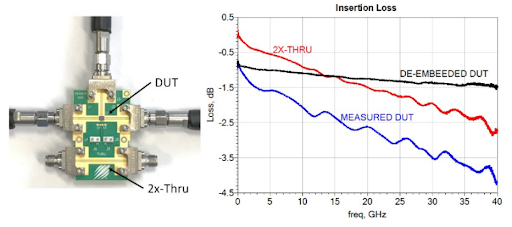
The de-embedding procedure uses an open access library of gold-standard S-parameters for standard test structures specified in the IEEE P370 standard. Because the test structure S-parameters are known or supplied by the standard, then the test structure S-parameters can be removed from the (DUT + test structure) S-parameters. This gives just the S-parameters of the DUT, as shown in the example below.
S-parameter Quality
The quality of an S-parameter matrix is defined in the following three areas:
- Causality. When used to construct an impulse response with a standardized method, the S-parameters should not produce causal artifacts in the time-domain response.
- Reciprocity. If the DUT in question is indeed reciprocal, then the S-parameters must also be reciprocal, i.e., the S-parameter matrix is equal to its own transpose.
- Passivity. This is related to reciprocity in that a reciprocal network must also be a passive network. S-parameters need to be evaluated for passivity, meaning they are not functions of the input signal strength.
By setting limits on these quality metrics, designers who receive S-parameter data for their components or who place passive structures on their PCBs can be assured their simulations will be accurate. This solves a major problem of inconsistent S-parameter data.
Placing Test Structures on Your PCB
The standards outlined here are only design and analysis standards as part of test and measurement, which will ultimately aid simulation in field solvers. When you’re ready to create your PCB with the test structures shown here, the advanced PCB layout utilities you’ll find in Altium Designer® can be used to create accurate test structures for high speed PCBs. You’ll also be able to quickly prepare your boards for manufacturing and assembly.
Once you’ve created your board or test coupon with IEEE P370 compliant test structures, you can share your design data on the Altium 365® platform, giving you an easy way to work with a remote team and manage your design data. We have only scratched the surface of what is possible to do with Altium Designer on Altium 365. You can check the product page for a more in-depth feature description or one of the On-Demand Webinars.